Table of Contents
Advertisement
Quick Links
Advertisement
Table of Contents

Related Manuals for myGekko SLIDE 2


Summary of Contents for myGekko SLIDE 2
- Page 1 SLIDE 2 SLIDE 2 Technical manual Technical manual...
-
Page 2: Table Of Contents
COM Port 1..................9 COM Port 2..................9 LAN....................10 USB....................10 Digital input...................11 Digital output................11 Audio Line Out................12 Assembly..................13 Accessories for SLIDE 2..............14 Cavity wall installation..............15 Configuration.................. 16 Network Settings................17 Device settings................18 Display...................18 Slider buttons................18 VoIP station.................. 19 7.3.1... -
Page 3: Safety And Warranty
Safety and warranty These reliable devices are built according to the current rules of technology. They were tested and left the factory in perfect condition. However, there are residual risks. Read and follow the safety instructions to avoid hazards. Ekon GmbH assumes no liability for damages caused by non-observance of safety instructions. - Page 4 DANGER Electrical Voltage! Danger to life and fire due to electrical voltage Inside the device are unprotected live components. Observe the VDE regu- lations. Disconnect all cables to be installed and take precautions against unintentional switching on. Do not operate the device if damaged. Decom- mission the device or system and secure it against unintentional operation if it can be assumed that safe operation is no longer guaranteed.
-
Page 5: General
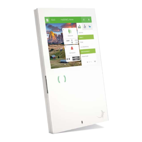
General The myGEKKO SLIDE 2 is a display controller for the implementation of all areas of modern building control. The combination of numerous complex control algorithms with a user-friendly and easy-to-understand interface enables the visualization and operation of the various building functions. All adjustments can be made by the customer directly on the display. - Page 6 You will receive accurate information about consumption and costs and can react immediately accordingly. Human - House - With myGEKKO you get a system that you understand and with which it is easy Technology to gain experience. The touch operation, the flexible configuration, and the...
-
Page 7: Technical Data
Technical data Parameters Value Housing Glass Color White Assembly Cavity wall, concealed Dimensions (WxHxD) 220 x 320 x 20 mm Weight ca. 1.5 kg Operating temperature +10°C to +35°C Storage temperature -20°C to 50°C Ambient humidity Max. 65% rh (without condensation) Operating life Continuous operation Power supply... - Page 8 Parameters Value Degree of soiling CE according to 2004/108/EC Certifications EN60529 EN60664 EN62262 EN55022 EN55024 EN61000-6-2 EN60730-1 EN60950-1 Connection...
-
Page 9: Com Port 1
COM Port 1 The COM Port 1 can be used as RS232 OR as RS485 interface. All myGEKKO compatible RS485 devices can be connected. Parameters Value Interface RS485 or RS232 Baud rate 9,600, 19,200, 38,400, 57,600 and 115,200 Parity adjustable COM Port 2 The COM Port 2 is an RS485 interface at the myGEKKO. -
Page 10: Lan
The myGEKKO can be connected to the network via the LAN interface Parameters Value Ethernet type 10/100 base T The myGEKKO SLIDE 2 has 2 USB interfaces with 500 mA each at the bottom. At the back there is another USB interface with 500 mA available. Parameters Value USB Type... -
Page 11: Digital Input
Digital input The digital input can be used with 24V DC input voltage. Parameters Value Input Optically isolated circuit insulation voltage 1 kV Input voltage 24 V DC Switching point <5V DC Digital output The digital output can be used as potential-free contact. Parameters Value Output voltage... -
Page 12: Audio Line Out
Audio Line Out A line out signal (left and right) can be taken. NOTE Attention, to avoid disturbances on the LineOut signal, the ground must be connected to the LINEOUT_GND. -
Page 13: Assembly
Assembly Ideal mounting The display is ideally mounted at the user's eye level for easy operation. Too height deep mounting can lead to back problems. Recessed Attach the holder to the UP socket mounting with appropriate screws. Hang the display on the holder. ... -
Page 14: Accessories For Slide 2
W x H x D: 200 x 320 x 75 Article: GEK.EBC.HWS.5101 Flush mounting The flush mounting box can be used box for the to install the myGEKKO Slide 2 in dry- myGEKKO SLIDE 2 wall construction. During installation, a 4 mm shadow gap is created for the display. -
Page 15: Cavity Wall Installation
Cavity wall installation Installation Description for cavity wall mounting For cavity wall mounting, a hole measuring 200 mm x 320 mm x 75 mm must be created, in which the housing can be inserted. 1. The cavity wall box is fastened with four clamping screws or metal claws on the sides. -
Page 16: Configuration
Configuration Access User: w Administrator: ww Configurator: mygekko There are the following options to access the myGEKKO Slide 2: Directly over the display Viewer Live Viewer Live Web DI & DO at the In the IO configuration you will find all the inputs and outputs that are directly myGEKKO SLIDE 2 on the myGEKKO Slide 2 under the menu item "ONBORD". -
Page 17: Network Settings
When resetting to factory settings, the I/O configuration will not be changed. Netzwerk: LAN DHCP Local Web Access HTTP/HTTPS: Locked VNC: Locked myGEKKO Viewer: Locked myGEKKO Net: Locked LAN Static If the network type is set to LAN Static, the following IP addresses are adopted by default. -
Page 18: Device Settings
Device settings Display 1. Define the desired display contrast for switching on and off. If you do not specify a value, the display is switched off upon shutdown. You can also set the time after which the shutdown is executed and define the shutdown behavior. -
Page 19: Voip Station
VoIP station VOIP (Voice over IP) stands for telephoning over the network/Internet. myGEKKO can be used as a VOIP videophone and communicate with other VOIP-enabled devices. The main application is the connection of VOIP indoor telephones to implement a video intercom system. -
Page 20: Video Settings
is also possible to communicate with other VOIP-capable devices. 7.3.1 Video Settings Indoor units can be optimally integrated via the camera menu. If an incoming call of the indoor unit is detected with the defined user, the corresponding full screen of the camera is displayed. In addition, you can define a button name including a button action, such as a door opener. -
Page 21: Ringtone Setting
You can make the following settings here: You can define a ringtone including the maximum ringing time, the volume of the voice output, and the ringer of myGEKKO. Touch the Ringtone box to select one of the predefined ringtones. You can also define a maximum ringing time, the desired volume for the language and the ringtone. -
Page 22: List Of Connections
List of Connections Connecting terminal Description Notification COM Port 1 RS485/RS232 COM Port 2 RS485 Digital input DI 24V DC Digital output 24V DC Audio Line Out L Audio Line Out R ... -
Page 23: Notes
Notes... - Page 24 Technical manual SLIDE 2 MRK.THB.SLI.0001 - version 1.6 - Status 2020-11-04 myGEKKO | Ekon GmbH St. Lorenznerstr. 2 I-39031 Bruneck (BZ) Tel. +039 0474 551820 info@my.gekko.com www.my-gekko.com Ekon Vertriebs GmbH Fürstenrieder Str. 279a, D-81377 München Vertriebsbüro Eislingen Schillerstr. 21, D-73054 Eislingen...
Need help?
Do you have a question about the SLIDE 2 and is the answer not in the manual?
Questions and answers