Table of Contents
Advertisement
Quick Links
Advertisement
Table of Contents

Related Manuals for Dual Pumps LCT12150PLR


Summary of Contents for Dual Pumps LCT12150PLR
- Page 1 793-1204 SERIES SERIES LCT12150PLR Original Manufacturer Instructions...
-
Page 2: Table Of Contents
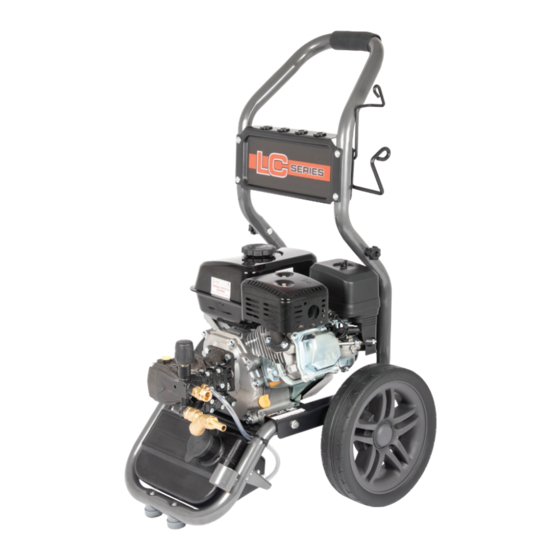
Introduction This manual and any other literature supplied must be read fully prior to the initial operation of your machine and be stored for later use or for subsequent owners. Pay particular attention to any instructions relating to operation and safety and maintenance of the unit. - Page 3 1. Component Identification - Main Machine (1) 1-11 1-10 1-12 1-13 1-14 Item No. Main Machine Photos Trolley Frame Trolley Wheels Engine High Pressure Pump Engine Oil Dipstick & Filler Engine Ignition On/Off Switch Engine Recoil Starter Pull Cord Engine Fuel Tank Fuel Filler Cap 1-10 Engine Choke Lever...
-
Page 4: Component Identification
1. Component Identification - Pump Close Up (2) & Accessories (3) Item No. Pump Close up Unloader Valve & Pressure Adjustor Knob Oil Breather Dipstick Suction Filter Suction Filter Inlet High Pressure Outlet Chemical Injector Engine Oil Cap & Dipstick 3-11 3-10 3-12... -
Page 5: Technical Specification
2. Technical Specification Model No. LCT12150PLR Engine Loncin G200-F Fuel Petrol Power 6.5 HP (4.85 kW) - SAE J1349 Nominal Rpm 3400-3600 Starting Method Recoil start Fuel Tank 3.6 Litres Max Feed Temperature 40°C Minimum Feed Flow Rate 15 Lpm... -
Page 6: Intended And Proper Use - Commercial
3. Intended and Proper Use - Commercial This machine is intended for Commercial use and is not suitable for normal housekeeping purposes by private persons whereby there may be a source of danger to the public. The machine must be used solely by professional contractors who are properly trained and wearing protective clothing to the required health &... -
Page 7: Safety Devices
This machine has been designed for use only with cleaning agents approved by the manufacturer. The use of other cleaning agents or chemicals may adversely affect the safety of the machine. High pressure jets can be dangerous if subject to misuse. The jet must not be directed at persons, animals, live electrical equipment or the machine itself. -
Page 8: Standard Accessories
6. Standard Accessories The LCT12150PLR pressure washer is supplied with the following accessories. Make sure all the items listed are included when unboxing for the first time. • Two part high pressure lance assembly. • 8m high pressure hose assembly. - Page 9 7. Pre-Operation Checks and Set Up ENGINE OIL - Use the engine dipstick to check the engine oil level, refer the engine manufacturers handbook for levels and oil types then add the required amount. FUEL - Fill the fuel tank with petrol fuel, refer to the engine manufacturers handbook for fuel types.
- Page 10 7. Pre-Operation Checks and Set Up SET UP Suction Hose Suction Hose Suction Hose Suction Hose Connect the suction filter and hose assembly to the suction filter hose barb with the supplied hose clip. Ensure all connections are tight and leak free.
-
Page 11: Start Up And Operation
8. Start Up and Operation Before starting the machine the user must be familiar with the engine starting and stopping procedure and any safety requirements stated in the engine manufacturer’s handbook supplied with the unit. ... -
Page 12: Stopping Procedure
8. Start Up and Operation WARNING: Do not let the pump idle in By-Pass for lengthy periods, if you intend to break from work for more than 5 minutes, switch the machine off. Should the machine run for a longer period, the temperature of the re- circulating water will increase rapidly and could risk damaging the pump seals. -
Page 13: Maintenance Information
12. Maintenance Information Maintenance and servicing of the machine must only be undertaken by suitably trained and qualified technicians. Unloader Valves must only be adjusted and serviced by suitably trained and qualified technicians. Ensure all steps from the Decommissioning & Storage section have been carried out before starting any work on the machine. -
Page 14: Troubleshooting
14. Troubleshooting Symptom Possible Cause Remedy Pump running normally Pressure Regulator valve Check and adjust but pressure low. Pump sucking air. Check water supply and possible air ingress. Lance in low pressure mode Check and adjust see page 9 Nozzle badly worn Check and/or replace Worn piston packing Seek professional advice... -
Page 15: Warranty Information
EN60335-2-79-2012 EN1829-1-2010 EN1829-2-2008 EN4871-2009 Manufacturer Dual Pumps Ltd, Saxby Road Industrial Estate, Melton Mowbray, LE13 1BS. United Kingdom Person authorised to compile the technical file & declaration Tom Herridge, Director Signed – Date – 12/01/2022 We hereby declare that the machinery described above complies with the relevant basic health and safety requirements of the UKCA &... - Page 16 Unit 8, Hudson Road Saxby Road Ind. Est. Melton Mowbray Leicestershire LE13 1BS Telephone: +44 (0)1664 567226 Fax: +44 (0)1664 410127 E-mail: info@dualpumps.co.uk www.dualpumps.co.uk...
Need help?
Do you have a question about the LCT12150PLR and is the answer not in the manual?
Questions and answers