Table of Contents
Advertisement
Advertisement
Table of Contents

Subscribe to Our Youtube Channel
Related Manuals for Dual Pumps THOR BLACK EDITION


Summary of Contents for Dual Pumps THOR BLACK EDITION
- Page 1 793-1150 Original Manufacturer Instructions...
-
Page 2: Table Of Contents
Introduction This manual and any other literature supplied must be read fully prior to the initial operation of your machine and be stored for later use or for subsequent owners. Pay particular attention to any instructions relating to operation and safety and maintenance of the unit. -
Page 3: Component Identification
1. Component Identification 1-12 1-10 1-11 1-4 & 1-5... - Page 4 1. Component Identification continued TBE41200DHE TBE25300DHE & TBE18400DHE TBE15500DHE...
- Page 5 1. Component Identification continued ACCESSORIES TBE25300DHE & TBE41200DHE TBE15500DHE & TBE18400DHE TBE25300DHE , TBE15500DHE & TBE18400DHE TBE41200DHE HATZ Engine Instrument Boxes Protective Cap Starting Key Pre-Glow Display (option) Air Filter Maintenance Display Engine Temperature Display (option) Oil Pressure Display Charge Control Operating Display Operating Hours Counter (option) Ignition Lock...
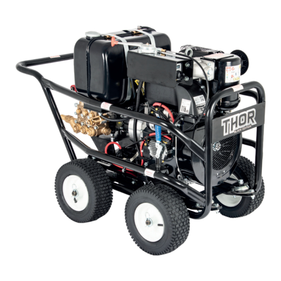
- Page 6 1. Component Identification continued Item No. Main Machine Photos Trolley Frame Trolley Baseplate on Anti-Vibration Rubbers Engine Gearbox Gearbox Oil Sight Glass High Presure Pump Throttle Control Lever Ignition Switch Panel Battery 1-10 Parking Brake Lever 1-11 Parking Brake Foot 1-12 Engine Oil Dipstick Gearbox Oil Dipstick/Breather...
-
Page 7: Technical Specification
2. Technical Specification Model No. TBE41200DHE TBE25300DHE TBE18400DHE TBE15500DHE Engine Hatz 2G40, Direct Injection, Air Cooled, Four Stroke Fuel Diesel Power 23.1 HP (17.0kW) - DIN ISO 1585 Nominal Rpm Engine 3400-3600 - Pump 1560-1650 via 2.176:1 gearbox Starting Method Electric Start Fuel Tank 21 Litres... -
Page 8: Intended And Proper Use - Commercial
3. Intended and Proper Use - Commercial This machine is intended for Commercial use and is not suitable for normal housekeeping purposes by private persons whereby there may be a source of danger to the public. The machine must be used solely by professional contractors who are properly trained and wearing protective clothing to the required health &... - Page 9 This machine has been designed for use only with cleaning agents approved by the manufacturer. The use of other cleaning agents or chemicals may adversely affect the safety of the machine. High pressure jets can be dangerous if subject to misuse. The jet must not be directed at persons, animals, live electrical equipment or the machine itself.
-
Page 10: Safety Devices
Risk of explosion! Do not put tools or similar on the battery, i.e. on the terminal poles and cell connectors. Risk of injury! Ensure that wounds never come into contact with lead. Always clean your hands after having worked with batteries. 5. -
Page 11: Pre-Operation Checks And Set Up
7. Pre-Operation Checks and Set Up CHECKS DAMAGE? Before each period of use ensure the machine and all components and accessories is complete and undamaged. Take care to ensure the suction hose and bypass hoses are kink-free. TRAVEL PLUGS - On the pump and gearbox REMOVE THE RED TRAVEL PLUGS and replace with the appropriate yellow-topped oil dipstick/breather Travel Plug Breather/Dipstick... - Page 12 7. Pre-Operation Checks and Set Up CHECKS FUEL - Fill the fuel tank with diesel fuel, refer the engine manufacturers handbook for fuel types. DO NOT USE BIOFUEL TYRES - Ensure all four tyres are BATTERY - Connect the battery leads, inflated to 2 Bar (30 psi).
- Page 13 7. Pre-Operation Checks and Set Up continued SET UP Connect the suction filter and hose assembly to the suction filter hose barb. Ensure all connections are tight and leak free. Air leaks on the suction side will impair the machine performance and damage components.
-
Page 14: Start Up And Operation
8. Start Up and Operation Before starting the machine the user must be familiar with the engine starting and stopping procedure and any safety requirements stated in the engine manufacturer’s handbook supplied with the unit. START ENGINE Ensure the engine throttle control lever Start the engine by turning key on the is fully forward for reduced engine Rpm. -
Page 15: Stopping Procedure
9. Stopping Procedure • DRAIN PUMP - Position the engine throttle control lever to reduce the engine Rpm. Remove the suction hose from the water supply tank and drain the water from the pump by allowing the machine to run for a few seconds with the trigger gun open until no water is coming from the high pressure jet. -
Page 16: Maintenance Information
12. Maintenance Information Maintenance and servicing of the machine must only be undertaken by suitably trained and qualified technicians. Unloader Valves and Safety Valves must only be adjusted and serviced by suitably trained and qualified technicians. Ensure all steps from the Decommissioning & Storage section have been carried out before starting any work on the machine. -
Page 17: Thor Pressure Washer Maintenance Schedule
13. Thor Pressure Washer Maintenance Schedule Each/ 3 months or 12 months or Activity First Use first 50 Hours 250 hours hours Inspect / top up oil levels Engine Gearbox Pump Air Filter and Oil Bath Level Change Oil Gearbox (SAE90 Gear Oil) Pump (SAE20/30 Pump Oil) (Change engine oil and filter (use SAE 15/40 Diesel Multigrade) in-line with the engine... -
Page 18: Troubleshooting
14. Troubleshooting Symptom Possible Cause Remedy Pump running normally Pressure Regulator valve Check and adjust but pressure low. Pump sucking air. Check water supply and possible air ingress. Nozzle badly worn Check and/or replace Worn piston packing Seek professional advice Fluctuating pressure Blocked water filter Check filter, clean or... -
Page 19: Warranty Information
EN60335-2-79-2012 EN1829-1-2010 EN1829-2-2008 EN4871-2009 Manufacturer Dual Pumps Ltd, Saxby Road Industrial Estate, Melton Mowbray, LE13 1BS. United Kingdom Person authorised to compile the technical file & declaration Tom Herridge, Director Signed – Date – 02/3/2020 We hereby declare that the machinery described above complies with the relevant basic health and safety requirements of the EU Directives, both in its’... - Page 20 Unit 8, Hudson Road Saxby Road Ind. Est. Melton Mowbray Leicestershire LE13 1BS Telephone: +44 (0)1664 567226 Fax: +44 (0)1664 410127 E-mail: info@dualpumps.co.uk www.dualpumps.co.uk...
Need help?
Do you have a question about the THOR BLACK EDITION and is the answer not in the manual?
Questions and answers