
Related Manuals for Endress+Hauser OTR31


Summary of Contents for Endress+Hauser OTR31
- Page 1 BA00229O/09/EN/15.20 71509927 2020-11-30 Valid as of version 01.02 (device version) Operating Instructions Temperature switch OTR31, OTR35 For safe measurement, monitoring and control of process temperatures...
-
Page 3: Table Of Contents
Temperature switch OTR31, OTR35 Table of contents Table of contents About this document ... 4 Accessories ....28 Document function . -
Page 4: About This Document
About this document Temperature switch OTR31, OTR35 About this document Document function These Operating Instructions contain all the information that is required in various phases of the life cycle of the device: from product identification, incoming acceptance and storage, to mounting, connection, operation and commissioning through to troubleshooting, maintenance and disposal. - Page 5 Temperature switch OTR31, OTR35 About this document 1.2.3 Symbols for certain types of information Symbol Meaning Permitted Procedures, processes or actions that are permitted. Preferred Procedures, processes or actions that are preferred. Forbidden Procedures, processes or actions that are forbidden.
-
Page 6: Basic Safety Instructions
Basic safety instructions Temperature switch OTR31, OTR35 Basic safety instructions Requirements for the personnel The personnel for installation, commissioning, diagnostics and maintenance must fulfill the following requirements: ‣ Trained, qualified specialists must have a relevant qualification for this specific function and task. -
Page 7: Product Safety
Temperature switch OTR31, OTR35 Incoming acceptance and product identification Risk of injury! ‣ Operate the device in proper technical condition and fail-safe condition only. ‣ The operator is responsible for interference-free operation of the device. Modifications to the device Unauthorized modifications to the device are not permitted and can lead to unforeseeable dangers: ‣... -
Page 8: Product Identification
Compare and check the data on the nameplate of the device against the requirements of the measurement point. Name and address of manufacturer Name of manufacturer: Endress+Hauser Wetzer GmbH + Co. KG Address of manufacturer: Obere Wank 1, D-87484 Nesselwang or www.endress.com... -
Page 9: Certificates And Approvals
Temperature switch OTR31, OTR35 Mounting Certificates and approvals 3.5.1 CE mark The product meets the requirements of the harmonized European standards. As such, it complies with the legal specifications of the EC directives. The manufacturer confirms successful testing of the product by affixing to it the CE-mark. -
Page 10: Mounting The Device
Mounting Temperature switch OTR31, OTR35 Mounting the device 120 °C 120 °C ≥ 3° ≥ 3° A0011644 2 Installation options for temperature monitoring in pipelines Hexagonal screw of sensor module Temperature switch Temperature switch for use in hygienic processes 4.2.1... - Page 11 Temperature switch OTR31, OTR35 Mounting Ambient temperature range –40 to +85 °C (–40 to +185 °F) 4.2.2 Installation instructions when installing in hygienic processes R0.4 R0.4 A0044659 3 Detailed installation instructions for hygiene-compliant installation Milk pipe connection according to DIN 11851 (PL, PG, PH connection), only in conjunction with EHEDG-certified and self-centering sealing ring 1.1 Sensor with milk pipe connection...
-
Page 12: Electrical Connection
Electrical connection Temperature switch OTR31, OTR35 In the case of weld-in connections, exercise the necessary degree of care when performing the welding work on the process side: Use suitable welding material. Flush-weld or weld with welding radius ≥ 3.2 mm (0.13 in). - Page 13 Temperature switch OTR31, OTR35 Electrical connection A2’ L– L– A4’ 4...20mA 4...20mA L– L– A0043603 4 Pin assignment on M12x1 connector Item no. Output setting 1x PNP switch output 2 x PNP switch output R1 and m (R2) A2’...
- Page 14 Electrical connection Temperature switch OTR31, OTR35 5.1.2 DC voltage version with valve connector L– A0035798 Item no. Output setting 1x PNP switch output...
-
Page 15: Operating Options
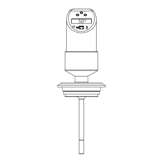
Temperature switch OTR31, OTR35 Operating options Operating options Local operation The device is operated via three keys. The digital display and the light emitting diodes (LED) assist navigation through the operating menu. A0044663 5 Position of the operating elements and possibilities for display Operating keys Digital display: illuminated white (= ok);... - Page 16 Operating options Temperature switch OTR31, OTR35 6.1.1 Navigation in the operating menu BASE > 3 s SAVE > 3 s A0035802 6 Navigation in the operating menu Function group selection Function selection To enter the operating menu, press the E key for longer than 3 s.
- Page 17 Temperature switch OTR31, OTR35 Operating options 6.1.2 Structure of the operating menu for 1x or 2x switch output BASE UNIT °C °F ZERO GET’Z DISP PVRO SPRO OFFR DESI FUNC WINC HYNC WINO HYNO TRSP OUT2 FNC2 WINC HYNC WINO...
- Page 18 Operating options Temperature switch OTR31, OTR35 6.1.3 Structure of the operating menu for 1x switch output and 1x analog output4 to 20 mA For devices with an analog output, both output 1 and output 2 can be configured as an analog...
- Page 19 Temperature switch OTR31, OTR35 Operating options A0008103 8 Operating menu: A function groups, B functions, C settings The function group 4-20 is available only if the 4 to 20 mAanalog output (4-20) is selected under FUNC or FNC2 in function group OUT or OUT2.
- Page 20 Operating options Temperature switch OTR31, OTR35 6.1.4 Basic settings Function Function Settings Description group BASE UNIT Technical unit °C Select unit on display: °F °C, °F, K factory setting: °C ZERO Zero point Position adjustment: configuration within ±10 °C/K (18 °F) of the upper sensor limit...
- Page 21 Temperature switch OTR31, OTR35 Operating options • Delay times for switch point SP and switchback point RSP can be configured in increments of 1 s. This makes it possible to filter out undesired temperature peaks of short duration or of high frequency.
- Page 22 Operating options Temperature switch OTR31, OTR35 Function group Function Settings Description FUNC Switching characteristics WINC WINC: Output 1 FNC2 HYNC Window/NC contact OUT2 WINO HYNC: Output 2, optional HYNO Hysteresis/NC contact WINO: Window/NO contact HYNO: Hysteresis/NO contact Factory setting: HYNO Switch point value Switch point –49.5 to 150 °C (–57.1 to 302 °F) in...
- Page 23 Temperature switch OTR31, OTR35 Operating options Function group Function Settings Description 4-20 SETL Value for 4 mA (LRV) –50 to 130 °C (–58 to 266 °F) Analog output Lower range value in increments of 0.1 °C/°F Factory setting: 0.0 °C (32 °F) SETU Value for 20 mA (URV) –30 to 150 °C (–22 to 302 °F)
-
Page 24: Access To The Operating Menu Via The Operating Tool
Operating options Temperature switch OTR31, OTR35 Access to the operating menu via the operating tool The device can be operated using the configuration software. This requires a configuration kit as a connection between the USB port of the PC and the device. -
Page 25: Diagnostics And Troubleshooting
Temperature switch OTR31, OTR35 Diagnostics and troubleshooting Diagnostics and troubleshooting General troubleshooting If an error occurs in the device, the color of the status LED changes from green to red and the lighting of the digital display from white to red. A flashing red/green status LED signals a warning. -
Page 26: Firmware History
Maintenance Temperature switch OTR31, OTR35 Code Description Remedial action W270 Short-circuit and overload at output 1 Check output wiring Increase the load resistance at switch output 1 W280 Short-circuit and overload at output 2 Check output wiring Increase the load resistance at switch output 2 Firmware history 7.2.1... -
Page 27: Cleaning
Temperature switch OTR31, OTR35 Repair Cleaning The device must be cleaned whenever necessary. Cleaning can also be done when the device is installed (e.g. CIP Cleaning in Place / SIP Sterilization in Place). When cleaning the device, care must be taken to ensure that it is not damaged. -
Page 28: Accessories
Accessories Temperature switch OTR31, OTR35 Accessories 10.1 Device-specific accessories 10.1.1 Welding boss with sealing taper • Collar welding boss movable with sealing taper, washer 6 (0.24) and pressure screw G½" G½” • Material of parts in contact with the process: 316L,... - Page 29 Temperature switch OTR31, OTR35 Accessories 10.1.3 Compression fitting • Movable clamping ring, various process connections 6 (0.24) • Material of compression fitting and parts in contact with the process: 316L • Order number: TA50-..(depending on the process AF14 connection) AF27 G½”...
-
Page 30: Communication-Specific Accessories
Accessories Temperature switch OTR31, OTR35 Version F in mm (in) L ~ in mm (in) C in B in mm Clampin Max. Max. process (in) g ring process pressure (in) material temperatur R½" SW/AF 22 52 (2.05) 20 (0.8) PTFE 200 °C... -
Page 31: Technical Data
Temperature switch OTR31, OTR35 Technical data • PVC cable (terminated), 4 x 0.34 mm with M12x1 coupling, elbowed, screw plug, length 5 m (16.4 ft) • Degree of protection: IP67 • Order number: 51005148 1 (BN) Core colors: 2 (WH) •... -
Page 32: Output
Technical data Temperature switch OTR31, OTR35 11.2 Output 11.2.1 Output signal DC voltage version (short-circuit proof version): • 1x PNP switch output • 2x PNP switch outputs • 1x PNP switch output or one PNP switch output and 4 to 20 mA output, active 11.2.2... -
Page 33: Power Supply
Temperature switch OTR31, OTR35 Technical data 11.3 Power supply 11.3.1 Supply voltage DC voltage version: 12 to 30 V (reverse polarity protection) Behavior in case of overvoltage (> 30 V) • The device works continuously up to 34 V without any damage •... -
Page 34: Process
Technical data Temperature switch OTR31, OTR35 11.5.1 Ambient temperature range –40 to +85 °C (–40 to +185 °F) 11.5.2 Storage temperature –40 to +85 °C (–40 to +185 °F) 11.5.3 Operating altitude Up to 4 000 m (13 123.36 ft) above sea level 11.5.4... - Page 35 Temperature switch OTR31, OTR35 Technical data Max. ambient temperature Max. process temperature up to 25 °C (77 °F) No restrictions up to 40 °C (104 °F) 135 °C (275 °F) up to 60 °C (140 °F) 120 °C (248 °F) up to 85 °C (185 °F)
- Page 36 Technical data Temperature switch OTR31, OTR35 v (ft/s) v (m/s) L (mm) L (in) A0008065 16 Permitted flow velocity Water Insertion length, during flow Flow velocity The permitted flow velocity is the minimum defined by the resonance velocity (resonance distance 80%) and stress or buckling caused by flow, which would lead to failure of the thermometer tube or to the safety factor (1.9) being exceeded.
-
Page 37: Mechanical Construction
Temperature switch OTR31, OTR35 Technical data 11.7 Mechanical construction 11.7.1 Design, dimensions 38.7 (1.52) 38.7 (1.52) 38.7 (1.52) 42.3 (1.66) 24 (0.95) 24 (0.95) 38.5 (1.52) 24 (0.95) 36 (1.42) 14 (0.55) 6 (0.24) 6 (0.24) 14 (0.55) 6 (0.24) 6 (0.24) - Page 38 Technical data Temperature switch OTR31, OTR35 11.7.2 Design, dimensions of process connections L1 = L2 A0007101 17 Process connection versions Insertion length Item Version Thread length L Screw-in length L Without process connection. Suitable welding bosses and compression fittings. → 28 Threaded process connection: •...
- Page 39 Temperature switch OTR31, OTR35 Technical data 56.5 (2.22) 70.5 (2.78) 43.5 (1.71) 77.5 (3.05) 64 (2.52) 50.5 (1.99) 61.5 (2.42) 68 (2.68) 50 (1.97) 82 (3.23) G½” 66 (2.6) 84 (3.31) 100 (3.94) 51 (2.01) 39 (1.54) (1.06) 68 (2.68) 56 (2.21)
-
Page 40: Certificates And Approvals
Technical data Temperature switch OTR31, OTR35 Item no. Process connection versions, hygiene version Hygiene standard DIN 11851, DN40, PN40 (including coupling nut) DIN 11851, DN50, PN40 (including coupling nut) Varivent® process connections are suitable for installation in VARINLINE® housing connection flanges. - Page 41 Temperature switch OTR31, OTR35 Technical data 11.8.2 Other standards and guidelines • IEC 60529: Degrees of protection provided by enclosures (IP code) • IEC/EN 61010-1: Protection Measures for Electrical Equipment for Measurement, Control, Regulation and Laboratory Procedures • IEC/EN 61326 series: Electromagnetic compatibility (EMC requirements) •...
- Page 44 *71509927* 71509927...
Need help?
Do you have a question about the OTR31 and is the answer not in the manual?
Questions and answers