Advertisement
Quick Links
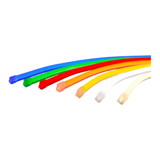
Contour
LED Lighting System
GEXNBL-1, GEXNGL-1, GEXNYG-1, GEXNRC-1, GEXNRD-1, GEXN65-1, GEXN32-1
BEFORE YOU BEGIN
Read these instructions completely and carefully.
RISK OF ELECTRIC SHOCK
• Disconnect power at fuse box or circuit breaker before servicing or installing product.
• Properly ground Tetra
power supply.
®
RISK OF FIRE
• Use only Tetra
supply wire to make connection from Tetra
®
• Use only approved wire for input/output connection. Minimum size 18 AWG (0.82mm
• Follow all local codes.
• Waterproof wire connection for outdoor or wet installations. See instructions for details.
• Do not stretch light engines.
• Inspect and replace the light engines if any tear or damage affects their integrity.
• Avoid installation that leads to prolonged exposure to standing water or ice.
RISK OF FIRE OR ELECTRIC SHOCK
• LED Retrofit Kit installation requires knowledge of sign electrical systems. If not qualified, do not attempt installation. Contact a qualified
electrician.
• Install this kit only in host signs that have been identified in the installation instructions and where the input rating of the retrofit kit does not
exceed the input rating of the sign.
• Installation of this LED retrofit kit may involve drilling or punching of holes into the structure of the sign. Check for enclosed wiring and
components to avoid damage to wiring and electrical parts.
• Do not make or alter any open holes in an enclosure of wiring or electrical components during kit installation.
Save These Instructions
Use only in the manner intended by the manufacturer.
If you have any questions, contact the manufacturer.
RETROFIT SIGN CONVERSION LED KIT FOR USE ONLY IN
ACCORDANCE WITH KIT INSTRUCTIONS.
KIT IS COMPLETE ONLY WHEN ALL PARTS REQUIRED BY
THE INSTRUCTIONS ARE PRESENT.
WARNING
power supply to Tetra
LED strip.
®
®
)
2
This device complies with part 15 of the FCC Rules. Operation is subject
to the following two conditions: (1) This device may not cause harmful
interference, and (2) this device must accept any interference received,
including interference that may cause undesired operation.
CAN ICES-005 (A) / NMB-005 (A)
Note: This equipment has been tested and found to comply with the
limits for a Class A digital device, pursuant to part 15 of the FCC Rules.
These limits are designed to provide reasonable protection against
harmful interference when the equipment is operated in a commercial
environment. This equipment generates, uses, and can radiate radio
frequency energy and, if not installed and used in accordance with
the instruction manual, may cause harmful interference to radio
communications. Operation of this equipment in a residential area
is likely to cause harmful interference in which case the user will be
required to correct the interference at his own expense.
Installation Guide
SIGN174EU | GE2024-0587
24
24
Volt
Advertisement

Related Manuals for Current Tetra GEXNBL-1


Summary of Contents for Current Tetra GEXNBL-1
- Page 1 Installation Guide SIGN174EU | GE2024-0587 Contour Volt LED Lighting System GEXNBL-1, GEXNGL-1, GEXNYG-1, GEXNRC-1, GEXNRD-1, GEXN65-1, GEXN32-1 BEFORE YOU BEGIN Read these instructions completely and carefully. WARNING RISK OF ELECTRIC SHOCK • Disconnect power at fuse box or circuit breaker before servicing or installing product. •...
- Page 2 Tetra Contour Installation Guide ® Prepare Electrical Wiring Electrical Requirements • Light engines without light guide limited to indoor dry locations. • Light engines with light guide acceptable to use in dry, damp or wet locations when installed correctly. • The grounding and bonding of the LED Driver shall be done in accordance with National Electric Code (NEC) Article 600.
-
Page 3: Installation
Tetra Contour Installation Guide ® METHOD A - Installing Light Engines With Light Guides Mounting orientation if moisture may accumulate Planning First inside light guide. Plan the layout by measuring the design layout and dividing by 8 ft . (2.44m) to determine the required quantity of Tetra Contour. - Page 4 Tetra Contour Installation Guide ® Connect four Connect two Separate wires + + – Light engine (back) negatives (–) positives (+) – Wire loops Light guide Wires between light guide segments To connect two light engines Use twist-on wire connectors to join can be folded behind the light guide separate wires and identify outer wires together.
-
Page 5: Connect Power Supply
Tetra Contour Installation Guide ® Connect Power Supply Outer wires (+) To Tetra Contour Middle wire (–) Red (+) Black or blue (–) Red (+) – Power Black or blue (–) supply To power supply Run a wire from the power supply Separate wires and identify outer Connect the two outer wires (+) to a section of Tetra Contour. - Page 6 Tetra Contour Installation Guide ® Installation 5-8 in. (127-203mm) Push into clips Install a mounting clip, using #6 Using the light engine final length, Push each 16 in. (406mm) light (M2) counter sink screws, every 5–8 measure out the necessary length engine segment into the clips.
- Page 7 Ensure that the branch circuit supplying the existing transformer or ballast will be within the voltage ratings of the new LED power supply, and have a current rating not exceeding 20A, or that permitted by applicable local, state, or country electrical codes (whichever is less).
-
Page 8: Troubleshooting
Tetra Contour Installation Guide ® Troubleshooting Symptom Condition Solution All LEDs are OFF No AC input. Attach AC input and/or check circuit breaker. Incorrect wire attachment. Check wire connection(s) at the Tetra Contour LED light engine and power supply for improper connections or short circuits. Make sure you have positive to positive and negative to negative wire connections. - Page 9 Tetra Contour Installation Guide ®...
- Page 10 Tetra Contour Installation Guide ®...
- Page 11 Tetra Contour Installation Guide ®...
- Page 12 Tetra Contour Installation Guide ®...
- Page 13 Tetra Contour Installation Guide ®...
- Page 14 Tetra Contour Installation Guide ®...
- Page 15 Tetra Contour Installation Guide ®...
- Page 16 Tetra Contour Installation Guide ®...
- Page 17 Tetra Contour Installation Guide ®...
- Page 18 Tetra Contour Installation Guide ®...
- Page 19 Tetra Contour Installation Guide ®...
- Page 20 Tetra Contour Installation Guide ®...
- Page 21 Tetra Contour Installation Guide ®...
- Page 22 Tetra Contour Installation Guide ®...
- Page 23 Tetra Contour Installation Guide ®...
- Page 24 Tetra Contour Installation Guide ®...
- Page 25 Tetra Contour Installation Guide ®...
- Page 26 Tetra Contour Installation Guide ®...
- Page 27 Tetra Contour Installation Guide ®...
- Page 28 Tetra Contour Installation Guide ®...
- Page 29 Tetra Contour Installation Guide ®...
- Page 30 Tetra Contour Installation Guide ®...
- Page 31 Tetra Contour Installation Guide ®...
- Page 32 Tetra Contour Installation Guide ®...
- Page 33 Tetra Contour Installation Guide ®...
- Page 34 Tetra Contour Installation Guide ®...
- Page 35 Dispose of the packaging in an environmentally friendly manner and make it available for the recyclable material collection-service. LED.com Page 35 of 35 (Rev 06/09/23) © 2023 Current Lighting Solutions, LLC. All rights reserved. Information and specifications subject to change SIGN174EU | GE2024-0587 without notice. All values are design or typical values when measured under laboratory conditions.
Need help?
Do you have a question about the Tetra GEXNBL-1 and is the answer not in the manual?
Questions and answers