Table of Contents
Advertisement
Quick Links
Advertisement
Table of Contents

Related Manuals for VAT 12150-PA24 ISO-320


Summary of Contents for VAT 12150-PA24 ISO-320
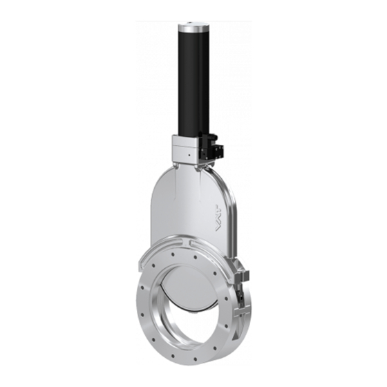
- Page 1 Installation, Operating & Maintenance Instructions Vacuum gate valve with double acting pneumatic actuator Series 121 DN 63 – 320 mm (I. D. 2½" – 12") This manual is valid for the following product ordering numbers: 121 .. - ..- ..Sample picture 600968EA Edition 2015-11-16...
- Page 2 VAT. Offenders are liable to pay damages. The original VAT firmware and updated state of the art versions of the VAT firmware are intended for use with VAT products. The VAT firmware contains a limited, time unlimited user license.
-
Page 3: Table Of Contents
Series 121 DESCRIPTION OF PRODUCT Contents Description of product ................ 4 Identification of product ..................4 Use of product ..................... 4 Related documents ..................... 4 Important information ..................4 Technical data ..................... 4 Safety ....................5 Compulsory reading material ................5 Danger levels ...................... -
Page 4: Description Of Product
• Dimensional drawing Important information This symbol points to a very important statement that requires particular attention. Example: VAT disclaims any liability for damages resulting from inappropriate packaging. Technical data See product data sheet and dimensional drawing. 4/27 Edition 2015-11-16... -
Page 5: Safety
Series 121 SAFETY Safety Compulsory reading material Read this chapter prior to performing any work with or on the product. It contains important information that is significant for your own personal safety. This chapter must have been read and understood by all persons who perform any kind of work with or on the product during any stage of its serviceable life. -
Page 6: Personnel Qualifications
SAFETY Series 121 Personnel qualifications WARNING Unqualified personnel Inappropriate handling may cause serious injury or property damage. Only qualified personnel are allowed to carry out the described work. Safety labels Label Part No. Location on valve T-9001-155 (DN 63 – 100) Protective cover T-9001-156 (DN 160 –... -
Page 7: Design And Function
Series 121 DESIGN AND FUNCTION Design and Function Design 1 Sealing surface 2 Valve body 3 Actuator 4 Position indicator 5 Solenoid valve Figure 3-1 Function The valve features the VATLOCK sealing technology. This means, the valve is mechani- cally locked in the closed position. In the open position, the mechanism is not locked. Leaf springs hold gate and counter plate against the carriage with the ball retainers. -
Page 8: Installation
• Make sure that the supplied products are in accordance with your order. • Inspect the quality of the supplied products visually. If it does not meet your requirements, please contact VAT immediately. • Store the original packaging material. It may be useful if products must be returned to VAT. - Page 9 NOTICE Too long screws Valve body may get deformed and / or malfunctions may occur. Use only screws recommended by VAT. Remove protective covers from body flanges. Clean sealing surfaces and seals of both flanges; see (1) and (2) according to «Figure 4-1».
-
Page 10: Admissible Forces And Bending Moments
«M» inch lbf · ft 2½ 1025 1080 3000 3000 3500 4000 If a combination of both forces («FA» and «M») occurs, the values mentioned above are invalid. Please contact VAT for more information. Table 4-1 10/27 Edition 2015-11-16 600968EA... -
Page 11: Compressed Air Connection
Series 121 INSTALLATION Compressed air connection WARNING Valve in open position Risk of injury when compressed air is connected to the valve. Connect compressed air only when: – valve is installed in the vacuum system – moving parts cannot be touched Use clean, dry or slightly oiled air only. -
Page 12: Operation
OPERATION Series 121 Operation WARNING Unqualified personnel Inappropriate handling may cause serious injury or property damage. Only qualified personnel are allowed to carry out the described work. WARNING Movable parts Human body parts may get jammed and severely injured. Do not operate before product is installed completely into the vacuum system. WARNING Hot surfaces Risk of burning when touching hot surfaces. -
Page 13: Manual Emergency Operation
Series 121 OPERATION 5.4.1 Manual emergency operation WARNING Movable parts Human body parts may get jammed and severely injured. Keep human body parts away from movable parts. Only valid for the ordering number 121..-..34/44 (with solenoid valve) In case of a power failure, the valve can be actuated manually if compressed air is available. -
Page 14: Trouble Shooting
OPERATION Series 121 Solenoid valve for impulse actuation (option) Press push-button (1): valve opens Press push -button (2): valve closes Trouble shooting Failure Check Action Valve does not Air pressure Connect «4.3 Compressed air close / open compressed air connection» Operating Adjust operating Product data sheet... -
Page 15: Maintenance
Maintenance intervals Under clean operating conditions the valve does not require any maintenance during the specified cycles; see product data sheet. After these cycles, VAT recommends replacing the mechanism unit; see chapter «6.4 Replacement of gate seal and bonnet seal». -
Page 16: Tightening Torque Specifications
MAINTENANCE Series 121 Tightening torque specifications Tightening torque [Nm] Item-No. Description DN 160–200 DN 250–320 Bonnet screw Tightening torque [Nm] Item-No. Description DN 63–100 Bonnet screw Table 6-1 Required tools • Torque wrench according «Table 6-1» • Cleanroom wiper soaked with alcohol (2% methyl ethyl ketone) •... - Page 17 Series 121 MAINTENANCE NOTICE Inappropriate tools Sealing surfaces may get damaged. Do not use sharp-edged tools. The numbers in brackets ( ) refer to «Figure 6-4» on page 19. Vent chambers on either side to atmospheric pressure. Open valve. Disconnect compressed air supply. Disconnect electrical power supply.
- Page 18 MAINTENANCE Series 121 11. Check and clean sealing surface of valve seat; use cleanroom wiper. 12. Install new gate seal (1); see «Figure 6-2». Press O-ring uniformly in crosswise order (diagonal) into groove. 13. Remove bonnet seal (3) from groove; use O-ring removal tool. 14.
- Page 19 Series 121 MAINTENANCE DN 63–100 DN 160 or higher Figure 6-3 19. For DN 160 or higher: Swing back both screws (2); see «Figure 6-4». 20. Tighten the screws (2) with the appropriate torque specified in chapter «6.2 Tightening torque specifications». 21.
-
Page 20: Repairs
Repairs may only be carried out by the VAT service staff. In exceptional cases, the customer is allowed to carry out the repairs, but only with the prior consent of VAT. Please contact one of our service centers. You will find the addresses on our website www.vatvalve.com. -
Page 21: Dismounting And Storage
Series 121 DISMOUNTING AND STORAGE Dismounting and Storage WARNING Unqualified personnel Inappropriate handling may cause serious injury or property damage. Only qualified personnel are allowed to carry out the described work. WARNING Heavy weight Physical overstraining. Use a crane to lift the product. WARNING Hazardous components Human body parts may get jammed and severely injured. -
Page 22: Dismounting
DISMOUNTING AND STORAGE Series 121 Dismounting NOTICE Valve in open position Valve mechanism may get damaged if valve is in open position. Close valve before dismounting the valve from the system. Close valve. Carry out the steps according to chapter «4 Installation» in reverse order. Pay attention to the safety instructions! Storage NOTICE... -
Page 23: Packaging And Transport
• If products are radioactively contaminated, the VAT form «Contamination and Radiation Report» must be filled out. Please contact VAT in advance. • If products are sent to VAT in contaminated condition, VAT will carry out the decontamination procedure at the customer's expense. -
Page 24: Packaging
Valve mechanism may get damaged if valve is in open position. Make sure that the valve is closed. Cover all valve openings with a protective foil. Pack valve appropriately, by using the original packaging material. VAT disclaims any liability for damages resulting from inappropriate packaging. Transport NOTICE Inappropriate packaging Product may get damaged if inappropriate packaging material is used. -
Page 25: Disposal
Series 121 DISPOSAL Disposal WARNING Harmful substances Environmental pollution. Discard products and parts according to the local regulations. 600968EA Edition 2015-11-16 25/27... -
Page 26: Spare Parts
«1.1 Identification of product». This is to ensure that the appropriate spare parts are supplied. • VAT makes a difference between spare parts that may be replaced by the customer and those that need to be replaced by the VAT service staff. - Page 27 «6.4 Replacement of gate seal and Bonnet flange O-ring on request bonnet seal» «6.4 Replacement of gate seal and O-ring removal tool 234859 bonnet seal» «6.4 Replacement of gate seal and VAT vacuum grease on request bonnet seal» Table 11-1 600968EA Edition 2015-11-16 27/27...
Need help?
Do you have a question about the 12150-PA24 ISO-320 and is the answer not in the manual?
Questions and answers