Table of Contents
Advertisement
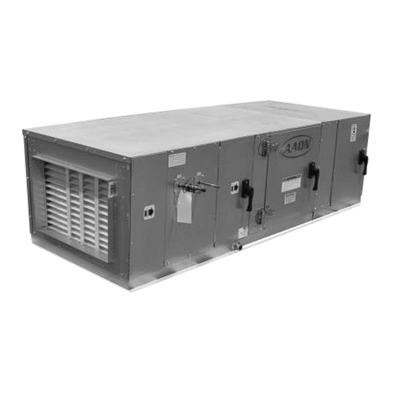
Horizontal Indoor Air Handling Units
UL60335
Installation, Operation
WARNING
QUALIFIED INSTALLER
Improper
installation,
alteration, service or maintenance can
cause property damage, personal
injury or loss of life. Startup and
service must be performed by a
Factory Trained Service Technician. A
copy of this IOM must be kept with the
unit.
& Maintenance
adjustment,
H3 Series
WARNING
If the information in this manual is not
followed exactly, a fire or explosion
may result causing property damage,
personal injury or loss of life.
WARNING
FOR YOUR SAFETY
Do not store or use gasoline or other
flammable vapors and liquids in the
vicinity of this or any other appliance.
Advertisement
Table of Contents

Related Manuals for AAON H3 Series


Summary of Contents for AAON H3 Series
- Page 1 H3 Series Horizontal Indoor Air Handling Units UL60335 Installation, Operation & Maintenance WARNING WARNING QUALIFIED INSTALLER If the information in this manual is not followed exactly, a fire or explosion Improper installation, adjustment, may result causing property damage, alteration, service or maintenance can personal injury or loss of life.
-
Page 2: Table Of Contents
Table of Contents Safety .............................. 6 H3 Base Model Description ......................11 General Information ........................17 Codes and Ordinances ....................... 18 Receiving Unit ........................... 18 Storage ............................19 Wiring Diagrams ........................19 Installation............................. 19 Locating the Unit ........................19 Lifting and Handling the Unit ....................23 Unit Assembly ........................... - Page 3 Replacement Parts ........................63 AAON ............................63 Filter Information .......................... 66 Refrigerant Piping Diagrams ......................70 H3 Series Startup Form ......................... 71 Maintenance Log .......................... 76 Maintenance Log (E-Coated Coil) ....................77 Literature Change History......................78 G117890 · Rev. A · 230810...
- Page 4 Table 31 - H3 Series E Cabinet Final Filters ................70 Table 32 - H3 Series Energy Recovery OA Filters (Feature 13 ≠ 0) ........... 70 Table 33 - H3 Series Energy Recovery RA Filters (Feature 13 ≠ 0) ........... 70...
- Page 5 Figures: Figure 1 - Lockable Handle ......................19 Figure 2 -Minimum Clearance Required for Access to Unit (H3 Series plan view) ....20 Figure 3 - H3 internal control panel with top access panel removed..........21 Figure 4 - H3 Series Platform Suspension Installation ..............21 Figure 5 - H3 Series Parallel Beam Suspension Installation ............
-
Page 6: Safety
Safety Attention must be paid to the following statements: NOTE - Notes are intended to clarify the unit installation, operation and maintenance. CAUTION - Caution statements are given to prevent actions that may result in equipment damage, property damage, or personal injury. WARNING - Warning statements are given to prevent actions that could result in equipment damage, property damage, personal injury or death. - Page 7 CAUTION WARNING Unit power supply wire must be only GROUNDING REQUIRED copper or aluminum. All field installed wiring must be completed by qualified personnel. WARNING Field installed wiring must comply with NEC/CEC, local and state electrical During installation, testing, servicing code requirements.
- Page 8 WARNING WARNING Some chemical coil cleaning Do not use oxygen, acetylene or air in compounds are caustic or toxic. Use place of refrigerant and dry nitrogen these substances only in accordance for leak testing. A violent explosion with manufacturer’s usage may result causing injury or death.
- Page 9 WARNING WARNING Never attempt to open an access door This appliance is not intended for use or remove a panel while the unit is by persons with reduced physical, running. Pressure in the unit can sensory or mental capabilities, or lack cause excessive force against the of experience and knowledge, unless panel.
- Page 10 SAFETY PRECAUTIONS overload settings. These are set by PROVIDED THROUGHOUT THIS the AAON factory for the protection of MANUAL. these motors/compressors and must not be adjusted over this factory 8. Keep this manual and all literature setpoint or bypassed. safeguarded near or on the unit.
-
Page 11: H3 Base Model Description
H3/V3 Series Feature String Nomenclature Model Options Unit Feature Options H3 - A R B - 3 - 0 - 1 6 1 C - 1 2 F : A A B B - 0 C 0 - F T B - 0 G 0 - 0 0 A A A C 0 0 B A 0 0 0 0 0 0 0 0 H3 Base Model Description BASE MODEL... - Page 12 D= Field Installed Controls by Others + Isolation M = Quarter Serpentine 8 fpi Relays N = Single Serpentine 10 fpi E = VCC-X AAON Orion Controls System P = Half Serpentine 10 fpi R = Quarter Serpentine 10 fpi Feature 1: SUPPLY FAN...
- Page 13 H3 Series Feature String Nomenclature Model Options Unit Feature Options H3 - A R B - 3 - 0 - 1 6 1 D - 4 1 F H G A - 0 0 0 A A B C -...
- Page 14 H3 Series Feature String Nomenclature Model Options Unit Feature Options H3 - A R B - 3 - 0 - 1 6 1 D - 4 1 F 0 A 0 - D 0 A 0 0 A A B C - H G A - 0 0 0 -...
- Page 15 H3/V3 Series Feature String Nomenclature Model Options Unit Feature Options H3 - A R B - 3 - 0 - 1 6 1 C - 1 2 F C 0 0 B A A B B - 0 C 0 - F T B - 0 G 0 - 0 0 A A A A 0 0 0 0 0 0 0 0 Feature 12: TONNAGE...
- Page 16 H3/V3 Series Feature String Nomenclature Model Options Unit Feature Options H3 - A R B - 3 - 0 - 1 6 1 C - 1 2 F A A B B - 0 C 0 - F T B - 0 G 0 - 0 0 A A A C 0 0 B 0 0 0 0 0 A 0 0 0 Feature 19: EXHAUST FAN...
-
Page 17: General Information
Units are assembled, wired, charged with dry nitrogen and run-tested at the This equipment is protected by a factory. H3 Series units are not intended for standard limited warranty under the residential use. Startup and service must be condition... -
Page 18: Codes And Ordinances
Codes and Ordinances WARNING H3 Series units have been tested and certified, by ETL, in accordance with UL Coils and sheet metal surfaces Safety Standard 60335-2-40 4th Edition, present sharp edges and care must ANSI Safety Standard Z21.47-2016. taken when... -
Page 19: Storage
Installation nuts and bolts to prevent unauthorized access. AAON equipment has been designed for quick and easy installation. Startup and service must be performed by Factory Trained Service Technician. The H3 unit can either be shipped assembled or shipped in sections. -
Page 20: Table 1 - H3 Series Clearances (Metric)
See Access Side Table 3 for access dimensions. Unit Size H3-A 0.8 m 2.7 ft Table 1 - H3 Series Clearances (Metric) H3-B 1.1 m 3.7 ft Access Side H3-C 1.6 m 5.2 ft... -
Page 21: Figure 3 - H3 Internal Control Panel With Top Access Panel Removed
Other installation sound. provisions may be necessary according to job specifications. Figure 4 - H3 Series Platform Suspension Installation... -
Page 22: Figure 5 - H3 Series Parallel Beam Suspension Installation
Figure 5 - H3 Series Parallel Beam Suspension Installation H3 Series Top View Left Hand Side Return Air Supply Air Air Flow “Back” “Front” Right Hand Side Connections and service access on right side for Consider the air flow to be right hand orientation hitting the back of your head. -
Page 23: Lifting And Handling The Unit
2. Connect Power and Control Wiring UNIT HANDLING between sections Incorrect lifting can cause damage to H3 Series units are equipped with low and the unit, injury or death. Lifting high voltage quick connects to connect equipment capacity must exceed unit wiring from one section to the next. -
Page 24: Figure 9 - Apply Gasket
H3 Series units are equipped with a single point power connection. Wiring from the unit to external controls and power sources must be provided in the field. 3. Connect Sections Remove the access side panel from the mixing box by removing the screws. It is also helpful to remove the access side panel from the air handling unit module. -
Page 25: Control Box
Control Box Some H3 units include an external control box that must be mounted in the field. The control box is designed with two mounting holes on the back panel. Make sure the wall fasteners can hold the weight of the control box. -
Page 26: Electrical
Electrical Verify the unit nameplate agrees with power supply. Connect power and control field wiring as shown on the unit specific wiring diagram provided laminated and attached to the door in the controls compartment. Table 4 - Nameplate Voltage Markings & Tolerances Acceptable Performance Nominal Operating Voltage Range... -
Page 27: Figure 16 - H3 Internal Control Panel Electrical Connections
it. Use the following procedure to cut a round On units with internal control panel, hole in a foam panel. electrical supply can enter through the supply Cutting Electrical Openings air side (front) of the H3 unit. 1. Locate the placement of the hole. Be sure that the conduit will not interfere with the operation of any component or prevent access of any door or removable... - Page 28 All wiring beyond this technician at startup and any wiring point has been completed by AAON and alteration must only be made at the cannot be modified without effecting the unit power connection. unit’s agency/safety certification.
-
Page 29: Duct Connection
wiring use the following chart to determine the allowable wiring distances. Table 6 - 35 KAIC Fuse Sizing Table 5 - Control Wiring 35 KAIC Construction Wire Size Interrupting Total Wire Distance Component Description (Standard) Rating (kA) Allowable Copper Class CC, Fuse Conductors Only 600V, 0.5A - 30A... -
Page 30: Condensate Drain Piping
For condensate drain lines, the line must be the same pipe size or larger than the drain connection, include a p-trap, and pitch downward toward drain. Use an air break with long runs of condensate lines. Installation section of this manual for more information. -
Page 31: Startup
-3.50 4.50 2.25 Supply Fans -4.00 5.00 2.50 H3 Series units are equipped with direct drive backward curved plenum supply Startup assemblies that deliver the air volume (See back of the manual for startup form) specified according to unit size and job requirements. -
Page 32: Figure 18 - Typical Wiring Diagram With Ec Motor
Electrically Commutated Motor Airflow ECat submittal. Typically, this max speed Adjustment will be the rpm set at the factory. The fan speed can be modulated using the 0-10 VDC input signal. To check fan output from the factory, the potentiometer can be dialed to 100%. By sending a 5V signal*, for instance, the rpm can be measured and this reading can be Figure 18 - Typical wiring diagram with EC... -
Page 33: Operation
Chilled Water or Non-Compressorized Operation DX Cooling Operation Unit operations must be controlled with Valve controls for chilled water cooling coil thermostat or unit controller, never at the and non-compressorized DX coil are by main power supply, except for emergency or others. -
Page 34: Dx Cooling
Winterizing Coils coverage for fin and tube and microchannel In some cases it may be necessary to coils. See the AAON E-Coated Coil winterize water coils to prevent them from Maintenance Record sheet. freezing. - Page 35 The Enviro-Coil Cleaner: AAON PN: V82540 force of the water or air jet may bend the fin edges and increase airside GulfClean ™ Coil Cleaner ; AAON PN: pressure drop. Reduced unit...
-
Page 36: Options
product is not intended for use as a Options degreaser. Any grease or oil film must first be removed with GulfClean ™ Coil Cleaner. Heating Coils One or two row hot water and steam heating Remove Barrier - First ensure the power to and preheating coils can be factory installed. -
Page 37: Chilled Water Coil
Table 11 - Hot Water Coil Sweat Chilled Water Coil Connection Sizes Factory installed four, six or eight row chilled water cooling coils can be factory mounted. Model Supply and Return These coils are supplied from a building (H3-) Connection Size (OD) chilled water source. -
Page 38: Direct Expansion (Dx) Systems
CAUTION WARNING CRANKCASE HEATER Piping shall be in accordance with OPERATION national and local codes. Pressure limiting devices, backflow preventers Some units equipped with and all other safety requirements are compressor crankcase heaters, which the sole responsibility of the installing must be energized at least 24 hours contractor. -
Page 39: Evaporator Coil
DX systems that need humidity control. sweating those caps. Immediately couple the The AAON modulating hot gas reheat system tubing to the indoor unit to avoid exposing diverts hot discharge gas from the condenser the coils to moisture. -
Page 40: Purge Circuit
connector (ASC) to false load the evaporator Adjusting Refrigerant Charge when reduced suction pressure is sensed. Adjusting the charge of a system in the field Field piping between the condensing unit must be based on determination of liquid sub- and the evaporator is required. Line sizes cooling and evaporator superheat. -
Page 41: Table 14 - Acceptable Refrigeration Circuit Values
Table 14 - Acceptable Refrigeration Circuit After adding or removing charge the system Values must be allowed to stabilize, typically 10-15 Cooling Cooling minutes, before making other Mode Liquid Mode Liquid Sub-Cooling Sub-Cooling adjustments. Values (°C) Values (°F) Cooling Only Unit 4.4 - 8.3 8-15 The type of unit and options determine the... -
Page 42: Table 15 - Acceptable Microchannel Air-Cooled Condenser Coil Liquid Sub-Cooling Values
Table 15 - Acceptable Microchannel Air-Cooled Condenser Coil Liquid Sub-Cooling Values (Metric) Cooling Mode Liquid Sub-Cooling Values(°C) Evaporator Coil Saturation Temperature (°C) Ambient (°C) 10.0 12.8 5.0 - 7.8 4.4 - 7.2 4.4 - 7.2 3.9 - 6.7 2.8 - 5.6 19.4 5.6 - 8.3 5.0 - 7.8... - Page 43 Compare calculated superheat Correct an overcharged system by reducing acceptable cooling mode superheat values the amount of refrigerant in the system to between 4.4 and 8.3°C (8 - 15°F) for all lower the sub-cooling. system types. Superheat will increase with long suction line runs.
-
Page 44: Table 17 - R-410A Refrigerant Temperature-Pressure Chart (Metric)
Table 17 - R-410A Refrigerant Temperature-Pressure Chart (Metric) °C °C °C °C °C -6.7 539.9 928.8 23.3 1473.5 38.3 2213.3 53.3 3193.8 -6.1 551.6 946.0 23.9 1496.9 38.9 2245.0 53.9 3235.8 -5.6 564.0 963.2 24.4 1521.0 39.4 2276.7 54.4 3277.9 -5.0 576.4 10.0... -
Page 45: Table 18 - R-410A Refrigerant Temperature-Pressure Chart (Imperial)
Table 18 - R-410A Refrigerant Temperature-Pressure Chart (Imperial) °F PSIG °F PSIG °F PSIG °F PSIG °F PSIG 78.3 134.7 213.7 321.0 463.2 80.0 137.2 217.1 325.6 469.3 81.8 139.7 220.6 330.2 475.4 83.6 142.2 224.1 334.9 481.6 85.4 144.8 227.7 339.6 487.8... -
Page 46: Table 19 - R-454B Refrigerant Temperature-Pressure Chart (Metric)
Table 19 - R-454B Refrigerant Temperature-Pressure Chart (Metric) °C °C °C °C °C 1348.0 38.3 2034.6 -6.7 484.5 843.3 23.3 53.3 2946.9 1370.0 38.9 2064.1 -6.1 495.6 859.3 23.9 53.9 2985.7 1392.2 39.4 2093.9 -5.6 506.9 875.3 24.4 54.4 3024.9 1414.6 40.0 2123.9 55.0 -5.0... -
Page 47: Table 20 - R-454B Refrigerant Temperature-Pressure Chart (Imperial)
Table 20 - R-454B Refrigerant Temperature-Pressure Chart (Imperial) °F PSIG °F PSIG °F PSIG °F PSIG °F PSIG 427.4 70.3 122.3 195.5 295.1 433.0 71.9 124.6 198.7 299.4 73.5 127.0 201.9 303.7 438.7 75.2 129.3 205.2 308.0 444.5 76.8 131.7 208.5 312.5 450.3... -
Page 48: Energy Recovery Units
Energy Recovery Units By carefully reviewing the information Some H3 units have been equipped with an within this section and following the energy recovery wheel. This section is instructions, the risk of improper operation provided to assure the energy recovery and/or component damage... -
Page 49: Polymer Energy Recovery Wheel
Polymer Energy Recovery Wheel Polymer Wheel Set Purge Angle This section is provided to assure the energy When installed, the purge angle is factory set recovery feature will be properly setup to to 5 degrees. If a different angle is required, perform in accordance with the job... - Page 50 Polymer Wheel to Air Seal Clearance To check wheel to seal clearance; first disconnect power to the unit, in some units the energy recovery wheel assembly can be pulled out from the cabinet to view the air seals. On larger units, the energy recovery wheel may be accessible inside the walk-in cabinet.
- Page 51 3. With hands and objects away from Frame Bearing beams shown racked moving parts, activate unit and confirm wheel rotation. Wheel rotates clockwise (as viewed from the pulley side). Wheel 4. If wheel has difficulty starting, turn power off and inspect for excessive interference between the wheel surface Bearing and each of the four (4) diameter seals.
- Page 52 • Use a brush or vacuum cleaner to remove small materials. • Use compressed air at a distance of at least 0.6 m (2 ft) from the wheel. Too much pressure can easily damage the aluminum media. • First remove the energy recovery wheel from the unit.
-
Page 53: Figure 28 - Wheel Segment Removal Pattern
removing opposing segments for even weight To install wheel segments, follow the steps distribution. Failure to maintain control of below. Reverse procedure for segment the wheel rotation while removing or removal. installing all segments could cause severe 1. Disconnect power from the wheel. injury to fingers or hands. - Page 54 Polymer Wheel Drive Motor and Pulley Polymer Wheel Air Seals Replacement Four adjustable diameter seals are provided 1. Disconnect power to wheel drive on each cassette to minimize transfer of air motor. between the counter flowing airstreams. 2. Remove belt from pulley and position temporarily around wheel rim.
- Page 55 CAUTION Protect hands and belt from possible sharp edges of hole in Bearing Support Beam. 5. Loop the trailing end of the belt over the shaft (belt is partially through the opening). 6. Reinstall the bearing onto the wheel shaft, being careful to engage the two locating pins into the holes in the bearing support beam.
-
Page 56: Energy Recovery Wheel General Cleaning
ASHRAE’s Classes of Air categories, to Energy Recovery Wheel General Cleaning Routine maintenance of the Energy Recovery create a routine cleaning schedule. Wheel includes periodic cleaning of the Energy Recovery Wheel as well as inspection Class contaminant of the Air Seals and Wheel Drive concentration with inoffensive odor and Components. - Page 57 The energy recovery wheel is “self-cleaning” in latent energy (water vapor) transfer can with respect to dry particles due to its laminar occur in shorter periods of time in flow characteristics. Smaller particles pass applications such as moderate occupant through; larger particles land on the surface smoking or cooking facilities.
-
Page 58: Figure 29 - H3 A Or B Cabinet Energy Recovery Wheel
Return Air Filter Figure 29 - H3 A or B Cabinet Energy Recovery Wheel H3 size A & B return air filters - access through top and bottom of the filter box. Figure 30 - H3 A or B Cabinet Outside Air Filter Access H3 size A &... -
Page 59: Figure 31 - H3 C Cabinet Energy Recovery Wheel
Return Air Filter Figure 31 - H3 C Cabinet Energy Recovery Wheel Figure 32 - H3 C Cabinet Outside Air Filter Access H3 size C outside air filters - access through removing the sheet metal piece shown above, and removing another sheet metal piece once inside. -
Page 60: Electric Heating
Electric Heating The unit is designed to heat a given amount Adjust airflow after installation to obtain an of air while operating. If this amount of air is air temperature rise within the range greatly reduced, approximately 1/3 during specified on the unit rating plate at the the heating season, the electric heating coil required external static pressure. -
Page 61: Phase And Brownout Protection Module
Phase and Brownout Protection Module DPM Setup Procedure With the supply voltage active to the module, you can setup all of the DPM’s settings without the line voltage connected. To change the setpoint parameters use the right arrow key to advance forward through the setpoint parameters and the left arrow to backup if needed. - Page 62 Screens Manufacturer’s Screen R-K Electronics DPM v0.0.00 Average Voltage Screen VAvg Default – the default screen shows the real time voltage detected in each of the 3 phases: A-B B-C C-A Voltage Selection Screen (Vertical Format) Default = 460V, 3Ø 200, 1Ø;...
-
Page 63: Filter Replacement
Replacement Parts Filter Replacement Parts for AAON equipment may be obtained Monthly filter inspection is required to from your local representative maintain optimum unit efficiency. https://www.aaon.com/find-a-rep. When ordering parts, reference the unit serial number and part number. WARNING Electric shock hazard. Shut off all... -
Page 66: Filter Information
Filter Information Table 22 - H3 Series A Cabinet Unit Filters Feature 6B Qty. Size (cm) [in.] Type No Pre Filters (1) 40.6 x 63.5 x 5.1 Pleated MERV 8 [16 x 25 x 2] Pleated MERV 8 Pleated MERV 11 (1) 40.6 x 63.5 x 10.2... -
Page 67: Table 24 - H3 Series C Cabinet Unit Filters
Table 24 - H3 Series C Cabinet Unit Filters Feature 6B Qty. Size (cm) [in.] Type No Pre Filters (2) 50.8 x 50.8 x 5.1 and (1) 40.6 x 50.8 x 5.1 Pleated MERV 8 [20 x 20 x 2 and 16 x 20 x 2] Pleated MERV 8 (2) 50.8 x 50.8 x 10.2 and... -
Page 68: Table 26 - H3 Series E Cabinet Unit Filters
Table 26 - H3 Series E Cabinet Unit Filters Feature 6B Qty. Size (cm) [in.] Type No Pre Filters (6) 40.6 x 63.5 x 5.1 Pleated MERV 8 [16 x 25 x 2] Pleated MERV 8 Pleated MERV 11 (6) 40.6 x 63.5 x 10.2... -
Page 69: Table 29 - H3 Series C Cabinet Final Filters
Table 29 - H3 Series C Cabinet Final Filters Feature 6C Qty. Size (cm) [in.] Type No Final Filters (2) 50.8 x 50.8 x 5.1 and (1) 40.6 x 50.8 x 5.1 Pleated MERV 8 [20 x 20 x 2 and 16 x 20 x 2] (2) 50.8 x 50.8 x 30.5 and... -
Page 70: Refrigerant Piping Diagrams
Cartridge MERV 13 [16 x 25 x 2 and 16 x 25 x 12] Pleated MERV 8 and Cartridge MERV 14 Table 32 - H3 Series Energy Recovery OA Filters (Feature 13 ≠ 0) Unit Size Qty. Size (cm) [in.] Type (1) 70 x 30.5 x 5.1... -
Page 71: H3 Series Startup Form
H3 Series Startup Form Job Name:_____________________________________________ Date:____________ Address:____________________________________________________________________ ____________________________________________________________________________ Model Number:_______________________________________________________________ Serial Number:___________________________________________ Tag:______________ Startup Contractor:____________________________________________________________ Address:____________________________________________________________________ ______________________________________________________ Phone:_____________ Pre Startup Checklist Installing contractor must verify the following items. 1. Is there any visible shipping damage? 2. Is the unit level? 3. - Page 72 Ambient Temperature Ambient Dry Bulb Temperature ______°C/°F Ambient Wet Bulb Temperature ______°C/°F Voltage L1-L2 L2-L3 L1-L3 L1-Ground L2-Ground L3-Ground Supply Fan Assembly Alignment Check Rotation Nameplate Amps________ Number L1 Volts/Amps L2 Volts/Amps L3 Volts/Amps VFD Frequency________________ VAV Controls_________________ Power Exhaust Fan Assembly Alignment Check Rotation Nameplate Amps________...
- Page 73 Refrigeration System 1 - Cooling Mode Saturated Line Pressure Sub-cooling Superheat Temperature Temperature Discharge Suction Liquid Refrigeration System 2 - Cooling Mode Saturated Line Pressure Sub-cooling Superheat Temperature Temperature Discharge Suction Liquid Refrigeration System 3 - Cooling Mode Saturated Line Pressure Sub-cooling Superheat...
- Page 74 Air-Cooled Condenser Fans Alignment Check Rotation Nameplate Amps________ Number L1 Volts/Amps L2 Volts/Amps L3 Volts/Amps Refrigeration System 1 - Heating Mode (Heat Pump Only) Saturated Line Pressure Sub-cooling Superheat Temperature Temperature Discharge Suction Liquid Refrigeration System 2 - Heating Mode (Heat Pump Only) Saturated Line Pressure...
- Page 75 Water/Glycol System 1. Has the entire system been flushed and pressure checked? 2. Has the entire system been filled with fluid? 3. Has air been bled from the heat exchangers and piping? 4. Is the glycol the proper type and concentration (N/A if water)? 5.
-
Page 76: Maintenance Log
This log must be kept with the unit. It is the responsibility of the owner and/or maintenance/service contractor to document any service, repair or adjustments. AAON Service and Warranty Departments are available to advise and provide phone help for proper operation and replacement parts. -
Page 77: Maintenance Log (E-Coated Coil)
Maintenance Log (E-Coated Coil) -
Page 78: Literature Change History
Literature Change History September 2022 New H3 Series IOM. May 2023 Added metric conversions equivalents in text and tables. Added new warning labels. Added safety statements. Added KAIC tables for fuse sizing. Removed gas heating information. - Page 80 Parts: For replacement parts, please contact your local AAON Representative. It is the intent of AAON to provide accurate and current product information. However, in the interest of product improvement, AAON reserves the right to change pricing, specifications, and/or design of its product without notice, obligation, or liability.
Need help?
Do you have a question about the H3 Series and is the answer not in the manual?
Questions and answers
At what setting showing on magnahelic do you change filters?