Page 1
SA SERIES 
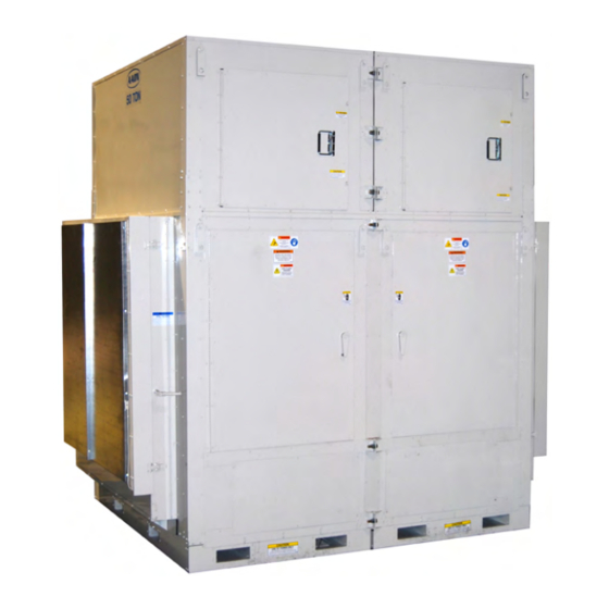
Vertical Self-Contained Units and Indoor Air Handling Units Installation, Operation & Maintenance WARNING If the information in this manual is not followed exactly, a fire or explosion WARNING may result causing property damage, personal injury or loss of life. QUALIFIED INSTALLER Improper installation,...
Table of Contents Safety .............................. 6 SA Series Feature String Nomenclature ..................11 General Information ........................16 Codes and Ordinances ....................... 16 Receiving Unit ........................... 16 Storage ............................17 Direct Expansion (DX) Systems ....................17 Wiring Diagrams ........................18 Condensate Drain Pans ......................18 Unit Size ............................
Page 4
Phase and Brownout Protection Module ................... 51 Filter Replacement ........................53 Replacement Parts ........................54 AAON Warranty, Service, and Parts Department ..............54 Appendix A - Heat Exchanger Corrosion Resistance ..............55 SA Series Startup Form ........................ 57 Maintenance Log .......................... 61 Literature Change History......................
Page 5
Index of Tables and Figures Tables: Table 1 - SA Series Models ......................18 Table 2 - Glycol Freezing Points ....................30 Table 3 - Condenser Water Connections ..................31 Table 4 - Condenser Pressure Drops (Each Heat Exchanger) ............32 Table 5 - Control Wiring.......................
Safety Attention should be paid to the following statements: NOTE - Notes are intended to clarify the unit installation, operation and maintenance. CAUTION - Caution statements are given to prevent actions that may result in equipment damage, property damage, or personal injury. WARNING - Warning statements are given to prevent actions that could result in equipment damage, property damage, personal injury or death.
Page 7
WARNING CAUTION During installation, testing, servicing Electric motor over-current protection and troubleshooting of the equipment and overload protection may be a it may be necessary to work with live function of the Variable Frequency electrical components. Only Drive to which the motors are wired. qualified licensed electrician...
Page 8
CAUTION WARNING Rotation must be checked on all Always use a pressure regulator, MOTORS AND COMPRESSORS of valves gauges control 3 phase units at startup by a qualified incoming pressures when pressure service technician. Scroll testing a system. Excessive pressure compressors are directional and can may cause line ruptures, equipment be damaged if rotated in the wrong...
Page 9
Failure of the condenser as a result with manufacturer’s usage of chemical corrosion is excluded instructions. Failure follow from coverage under AAON Inc. instructions may result in equipment warranties and the heat exchanger manufacturer’s warranties. damage, injury or death. WARNING CAUTION WATER FREEZING...
Page 10
2. The unit is for indoor use only. See WARNING General Information section for more unit information. COMPRESSOR CYCLING 3. Every unit has a unique equipment 5 MINUTE MINIMUM OFF TIME nameplate with electrical, operational, prevent motor overheating unit clearance specifications.
SA Series Feature String Nomenclature SA - 035 - 3 - A - E R 0 9 - 0 0 0 A C 0 0 - 0 0 0 - E B F - A B 0 0 0 0 0 0 0 0 - H A - 0 0 0 0 0 0 0 0 B SA Series Feature String No me nclature A2: Unit Configuration...
Page 12
SA Series Feature String Nomenclature 0 0 0 : A C 0 0 - 0 0 0 SA - 035 - 3 - A - E R 0 9 - - E B F - A B 0 0 0 0 0 0 0 0 - H A - 0 0 0 0 0 0 0 0 B B1: Heating Type 1C: Discharge Configuration...
Page 13
SA Series Feature String Nomenclature E B F - A B 0 - 0 0 0 0 0 0 SA - 035 - 3 - A - E R 0 9 - 0 0 0 A C 0 0 - 0 0 0 - 0 - H A - 0 0 0 0 0 0 0 0 B 5A: Supply Air Blower Configuration...
Page 14
SA Series Feature String Nomenclature 0 0 0 0 0 - H SA - 035 - 3 - A - E R 0 9 0 0 0 A C 0 0 - 0 0 0 - E B F - A B 0 A - 0 0 0 0 0 0 0 0 B 13: Special Controls...
Page 15
B = Standard Paint 0 = Standard U = Special Pricing Authorization + Special Paint A = Overflow Switch X = Special Pricing Authorization + AAON Gray B = UV Lights Paint C = Options A + B 17: Blank...
electrically grounded in accordance with General Information local codes, or in the absence of local codes, current National Electric Code, SA Series self contained units and indoor air ANSI/NFPA 70 or the current Canadian handling units have been designed for Electrical Code CSA C22.1.
Storage CAUTION If installation will not occur immediately following delivery, store equipment in a dry CRANKCASE HEATER protected area away from construction traffic and in the proper orientation as Some units equipped with marked on the packaging with all internal compressor crankcase heaters,...
Units require drain p-traps and lines to be combination of the four standard unit sizes, connected to the condensate drain pans of SA-023, SA-028, SA-030, and SA-035. the unit. The lines should be the same pipe size or larger than the drain connection, include a p-trap, and pitch downward toward drain.
Lifting and Handling the Unit Installation Before lifting unit, be sure that all shipping material has been removed from unit. Locating the Unit Placement of the unit relative to ductwork, WARNING electrical and plumbing must be carefully considered. Return air plenum or duct can be UNIT HANDLING mounted directly to the return air flanges.
to secure the coil sections together. See Split Unit Assembly Units may be split into modules for Figure 9. shipping. Fan and coil modules must be 4. Align and set each fan section on top of bolted together and factory provided splices the coil section(s).
-7°F -6°F freezing in the condenser is excluded from -28°F -27°F coverage under AAON warranties and the heat exchanger manufacturer warranties. Water loop piping runs through unheated areas or outside the building should be insulated. WARNING...
Table 3 - Condenser Water Connections CAUTION Supply and Return Model (SA-) Connection Size WATER PIPING 1 1/2” MPT 023, 045 028, 030, 035, 050, Follow national and local codes when 2” MPT 055, 058, 060, 065, installing water piping. Connections unit should incorporate...
Globe or gate valves should void warranty. not be used due to high pressure drops and poor throttling characteristics. Table 4 - Condenser Pressure Drops (Each Heat Exchanger) SA-023 SA-028 SA-030 SA-035 SA-045 SA-050 SA-055 SA-058...
located inside the controls compartment CAUTION door. exceed recommended WARNING condenser fluid flow rates shown in above table. Serious damage to or erosion of the heat exchanger tubes Disconnect electrical power could occur. sources before servicing the unit. More than one power source may be provided.
All wiring beyond 4. With a knife cut the foam out of the hole. this point has been completed by AAON and 5. After the conduit is installed in the hole cannot be modified without effecting the unit’s agency/safety certification.
Example: (221V+230V+227V)/3 226V, then If any factory installed wiring must be 100*(226V-221V)/226V = 2.2%, which replaced, use a minimum 105°C type AWM exceeds the allowable imbalance. insulated conductors. Check voltage imbalance at the unit Thermostat Control Wiring disconnect switch and at the compressor If a thermostat is used for unit control, terminal.
Example: and pitch downward toward drain. An air A total of 8 wires must be pulled 75ft to a break should be used with long runs of control the unit. What size wire should be condensate lines. used? CAUTION According to the Table 5, 16 AWG allows for 63ft (500 ft/8 wires) and 14 AWG allows Unit should not be operated without for 94ft (750 ft/8 wires).
the dirt allowance pressure drop for the During waterside economizer only mode of filters to account for the worst-case scenario. operation condenser water flows through the waterside economizer coil with modulating The height from top of the bottom bend of valves maintaining supply air temperature the trap to the bottom of the leaving pipe setpoint.
Waterside Economizer Piping Kit For single cabinet units connect the three factory provided piping assemblies. For dual cabinet units connect both sets of factory CAUTION provided piping assemblies. Installing contractor is responsible for Connect the piping assembly to the unit. properly sizing and installing water system components.
Hot Water Coil Startup Factory installed one or two row hot water (See back of the manual for startup form) heating coils can be factory mounted. These coils are supplied from a hot water source WARNING through separate piping from the condenser water source.
Fan assemblies are equipped with spring the adjustment bolt is turned (See Figure isolators in the fan section for vibration 17). attenuation. Turn adjustment bolt counter-clockwise to Prior to shipment the isolators are set in the adjust all four isolators until 3/4 inch lock down position to protect the unit during clearance is obtained between all spring transit.
Supply Fan Removal Hold Down WARNING Bracket Screws Disconnect electrical power sources before servicing the unit. More than one power source may be provided. Failure to do so may result in injury or death from electrical shock or entanglement in moving parts.
required, the band can be removed from the alteration to the wheel or blades occurs wheel. during the installation. Use fan program in AAONEcat32 to determine the new band size for the required cfm and static pressure. The following photos of a wheel are provided for practical guidelines only in order to identify the air band location in the wheel.
CAUTION The Clean Air Act of 1990 bans the intentional venting refrigerant (CFC’s and HCFC’s) as of July 1, 1992. Approved methods of recovery, recycling or reclaiming must be followed. Fines and/or incarceration may be levied for non-compliance. Units equipped with hot gas reheat must be charged with the hot gas reheat valves closed while the unit is in cooling mode to get the proper charge.
will vary from discharge pressure due to Table 8 - Acceptable Refrigerant Circuit condenser pressure drop. Values Air-Cooled Condenser/ Convert the pressure obtained to a saturated Air-Source Heat Pump temperature using the appropriate refrigerant Sub-Cooling 12-18°F temperature-pressure chart. Sub-Cooling with 15-22°F Hot Gas Reheat Subtract...
Operation Maintenance (See back of the manual for maintenance Unit operations should be controlled with log.) thermostat or unit controller, never at the main power supply, except for emergency or At least once each year, a qualified service complete shutdown of the unit. technician should check out the unit.
E-Coated Coil Cleaning CAUTION Documented routine cleaning of e-coated coils is required to maintain coating High velocity water from a pressure warranty coverage. washer or compressed air should Quarterly cleaning is essential to extend only be used at a very low pressure the life of an e-coated coil and is required to prevent fin and/or coil damages.
Recommended Chloride Remover Supply Fans CHLOR*RID DTS™ should be used to remove soluble salts from the e-coated coil, CAUTION but the directions must be followed closely. This product is not intended for use as a Blower wheels and bands must be degreaser.
Phase and Brownout Protection Module DPM Setup Procedure With the supply voltage active to the module, you can setup all of the DPM’s settings without the line voltage connected. To change the setpoint parameters use the right arrow key to advance forward through the setpoint parameters and the left arrow to backup if needed.
Page 52
Screens Manufacturer’s Screen R-K Electronics DPM v0.0.00 Average Voltage Screen VAvg Default – the default screen shows the real time voltage detected in each of the 3 phases: A-B B-C C-A Voltage Selection Screen (Vertical Format) Default = 460V, 3Ø 200, 1Ø;...
Filter Replacement panel and pull filters straight out to inspect Monthly filter inspection is required to all of the filters. Replace filters with the size maintain optimum unit efficiency. indicated on each filter or as shown in the tables below. Arrow on the replacement filters must point towards the blower.
Replacement Parts Parts for AAON equipment may be obtained from your local AAON representative. Reference the unit serial number and part number when ordering parts. AAON Warranty, Service, and Parts Department 2424 S. Yukon Ave. Tulsa, OK 74107 Ph: 918-382-6400 Fax: 918-382-6364 www.aaon.com...
Appendix A - Heat Exchanger Corrosion Resistance Corrosion Resistance of Copper and Stainless Steel in Brazed Plate Heat Exchangers - Points to Measure and Check in a Water Analysis The resistance guide below provides the corrosion resistance of stainless steel type AISI 316 and pure Copper (99.9%) in water, to a number of important chemical factors.
Page 56
Water Concentration Time Limits - AISI Copper Nickel Containing (mg/l or ppm) Analyze Before Alloy Alloy Total Hardness 4.0-8.5 No Limit (°dH) < 100 Nitrate (NO No Limit > 100 < 0.2 Iron (Fe) No Limit > 0.2 < 0.2 Aluminum (Al) No Limit >...
SA Series Startup Form Job Name:_______________________________________________ Date:______________ Address:______________________________________________________________________ ______________________________________________________________________________ Model Number:_________________________________________________________________ Serial Number:_____________________________________________ Tag:_______________ Startup Contractor:______________________________________________________________ Address:______________________________________________________________________ _______________________________________________________ Phone:______________ Pre Startup Checklist Installing contractor should verify the following items. 1. Is there any visible shipping damage? 2. Is the unit level? 3.
Page 58
Supply Fan Assembly Alignment Check Rotation Nameplate Amps________ Number Band Size_____________________ VAV Controls_________________ VFD Frequency________________ Springs Operating Correctly Compressors/DX Cooling Check Rotation Head Suction Number Pressure Pressure PSIG PSIG Refrigeration System 1 - Cooling Mode Saturated Line Pressure Sub-cooling Superheat Temperature Temperature Discharge...
Page 59
Refrigeration System 4 - Cooling Mode Saturated Line Pressure Sub-cooling Superheat Temperature Temperature Discharge Suction Liquid Refrigeration System 1 - Heating Mode (Heat Pump Only) Saturated Line Pressure Sub-cooling Superheat Temperature Temperature Discharge Suction Liquid Refrigeration System 2 - Heating Mode (Heat Pump Only) Saturated Line Pressure...
Page 60
Unit Configuration Water-Cooled Condenser Air-Cooled Condenser No Water Leaks Condenser Safety Check Water Flow ________ gpm Water Inlet Temperature ________°F Water Outlet Temperature ________°F Water/Glycol System 1. Has the entire system been flushed and pressure checked? 2. Has the entire system been filled with fluid? 3.
This log must be kept with the unit. It is the responsibility of the owner and/or maintenance/service contractor to document any service, repair or adjustments. AAON Service and Warranty Departments are available to advise and provide phone help for proper operation and replacement parts.
Literature Change History June 2010 Revision of the IOM adding PVC and CPVC piping Caution. February 2011 Revision of the IOM correcting the information about head pressure control, adding information about adjusting a heat pump unit’s refrigerant charge and adding information about assembling split units.
Page 64
Parts: For replacement parts please contact your local AAON Representative. It is the intent of AAON to provide accurate and current product information. However, in the interest of product improvement, AAON reserves the right to change pricing, specifications, and/or design of its product without notice, obligation, or liability.