Table of Contents
Advertisement
Quick Links
INSTALLATION, OPERATION
WARNING
If the information in this manual is not
followed exactly, a fire or explosion
may result causing property damage,
personal injury or loss of life.
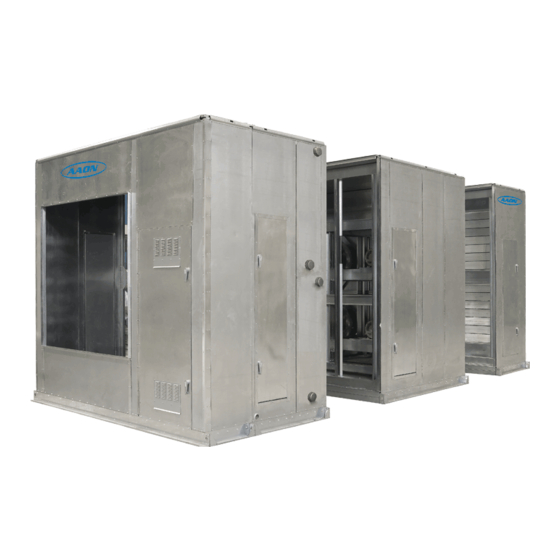
MODULAR AIR HANDLERS
&
MAINTENANCE
M3 SERIES
WARNING
FOR YOUR SAFETY
Do not store or use gasoline or other
flammable vapors and liquids in the
vicinity of this or any other appliance.
Advertisement
Table of Contents

Related Manuals for AAON M3 Series


Summary of Contents for AAON M3 Series
- Page 1 M3 SERIES MODULAR AIR HANDLERS INSTALLATION, OPERATION & MAINTENANCE WARNING WARNING If the information in this manual is not FOR YOUR SAFETY followed exactly, a fire or explosion Do not store or use gasoline or other may result causing property damage, flammable vapors and liquids in the personal injury or loss of life.
-
Page 3: Table Of Contents
External Control Panel………………………………………………………………………………50 Electrical……………………………………………………………………………………………. 51 Panel Cutting……………………………………………………………………………………….. 51 Dampers/Actuators…………………………………………………………………………………. 52 Duct System…………………………………………………………………………………………53 Piping………………………………………………………………………………………………..53 Operation………………………………………………………………………………………………. 54 Startup Checklist…………………………………………………………………………………….54 Procedures…………………………………………………………………………………………...54 Commissioning……………………………………………………………………………………... 54 Air Balancing………………………………………………………………………………………..55 Water Balancing……………………………………………………………………………………. 55 Controls……………………………………………………………………………………………...55 Maintenance…………………………………………………………………………………………….55 Routine Maintenance……………………………………………………………………………….. 56 Blower Assembly……………………………………………………………………………………56 Coils/Drain Pan……………………………………………………………………………………...56 Doors/Panels………………………………………………………………………………………... 58 Filters……………………………………………………………………………………………….. 59 M3 Series Startup Form………………………………………………………………………………...61... - Page 4 It is the intent of AAON to provide accurate and current product information. However, in the interest of product improvement, AAON reserves the right to change pricing, specifications, and/or design of its products without notice, obligation or liability Copyright © 2008 AAON, all rights reserved throughout the world.
-
Page 5: Unit Orientation
Unit Orientation Determine left hand or right hand orientation (connections): M3 Air Handler Top View Right Hand Side Supply Air Return Air AIRFLOW Supply Fan Coil Filter Connections & service access on left side for Left Hand Side left hand orientation Consider the airflow to be “hitting the back of your... -
Page 6: Model Number Nomenclature
Model Number Nomenclature Base Model Number Individual Module Model Numbers Identifies the main unit features and options. Identifies module configurations, features, and options. MBA-101-0-00-0F0A0-000A0-0-0 FMB-102-0-00-B00C0-00000-0-0 CLA-103-A-00-CNCA0-00000-0-0 M3-0-094-134x119-3-A-A-A-0-A-0 BMA-104-A-00-00000-00000-0-0 SFA-105-0-AA-CPTB0-00000-0-0 DPA-106-0-00-D0000-0000C-M-0 Complete Model Number The complete unit model number consists of air handler assembly, increasing in value a base model number followed by and series from the return/outside air section to the... -
Page 7: M3 Base Model Description
M3 Base Model Description Model Number BASE MODEL Digit 7, 8, 9, 10, 11, 12: CROSS SECTION 092 x 066 = 92” x 66” Digit 1: Series 092 x 079 = 92” x 79” M = Modular 092 x 089 = 92” x 89” 108 x 089 = 108”... - Page 8 M3 Base Model Description Model Number Digit 13: VOLTAGE Digit 17: CORROSION PROTECTION 2 = 230V/3Φ/60Hz 0 = No Paint 3 = 460V/3Φ/60Hz A = Interior Corrosion Protection 4 = 575V/3Φ/60Hz B = Exterior Corrosion Protection 6 = 380-415V/3Φ/50Hz C = Shipping Shrink Wrap 8 = 208V/3Φ/60Hz D = Options A + B E = Options A + C...
-
Page 9: Supply Fan Module Description
Supply Fan Module Description Model Number Digit 1, 2, 3: MODULE ID Digit 11: TYPE SFA = Supply Fan 0 = Standard Efficiency SFB = Supply Fan with Flat Filter Bank A = Premium Efficiency SFC = Supply Fan with External Control Panel B = Premium Eff with 1 VFD SFD = Supply Fan with Flat Filter Bank and External C = Premium Eff with 1 VFD and Bypass... - Page 10 Supply Fan Module Description Model Number BLOWERS AND MOTORS Digit 17: POWER SWITCH 0 = No Wiring Digit 13: BLOWER A = Power Block (No Power Switch) 0 = 24” Diameter B = 60 Amp Non-fused Disconnect Switch A = 27” Diameter C = 100 Amp Non-fused Disconnect Switch B = 30”...
- Page 11 Supply Fan Module Description Model Number Digit 18: CONTROL PANEL / OPENING Digit 20: ACCESS 0 = None 0 = Left Door, No Drain A = Left Control Panel A = Right Door, No Drain B = Right Control Panel B = Both Doors, No Drain C = Left Discharge Opening C = Left Door, Left Drain...
-
Page 12: Cooling/Preheat Coil Module Description
Cooling/Preheat Coil Module Description Model Number Digit 1, 2, 3: MODULE ID Digit 11: FPI CLA = Chilled Water Coils, External Connection, 0 = 8 FPI, 0.0060” Fin Thick, 0.017” Tube Wall Standard Drain Pan (30.5”) A = 10 FPI, 0.0060” Fin Thick, 0.017” Tube Wall CLC = Chilled Water Coils, Hydronic Preheat, B = 12 FPI, 0.0060”... - Page 13 Cooling/Preheat Coil Module Description Model Number COOLING COIL Digit 16: FPI 0 = No Preheat Coil Digit 12: CIRCUITING A = 8 FPI, 0.0060” Fin Thick, 0.017” Tube Wall 0 = Full Serpentine B = 10 FPI, 0.0060” Fin Thick, 0.017” Tube Wall A = Half Serpentine C = 12 FPI, 0.0060”...
- Page 14 Cooling/Preheat Coil Module Description Model Number Digit 17: TYPE Digit 20: ACCESS 0 = No Preheat Coil 0 = Left Door, Left Drain, Left Coil Connections A = Hot Water, Full Serpentine (2 Rows Only) A = Left Door, Left Drain, Right Coil Connections B = Hot Water, Half Serpentine B = Left Door, Right Drain, Left Coil Connections C = Hot Water, Quarter Serpentine...
-
Page 15: Heating Coil Module Description
Heating Coil Module Description Model Number Digit 1, 2, 3: MODULE ID Digit 9: STAGING HCA = Hot Water Coil, External Connections 0 = No Electric Heat HCB = Steam Coil, External Connections A = 2 Stage HCC = Electric Heat B = 3 Stage HCD = Hot Water Coil with Internal Face and C = 4 Stage... - Page 16 Heating Coil Module Description Model Number Heating Coil Digit 15: BLANK Digit 12: FPI 0 = Standard 0 = No Heating Coil A = 8 FPI, 0.0060” Fin Thick, 0.017” Tube Wall Digit 16: BLANK B = 10 FPI, 0.0060” Fin Thick, 0.017” Tube Wall 0 = Standard C = 12 FPI, 0.0060”...
-
Page 17: Blank Module Description
Blank Module Description Model Number Digit 1, 2, 3: MODULE ID Digit 9: BLANK BMA = 2’ Access Section 0 = Standard BMB = 2.5’ Access Section BMC = 3’ Access Section Digit 10: DRAIN PAN BMD = 4’ Access Section 0 = None A = Stainless Steel Drain Pan Digit 4, 5, 6: POSTION... - Page 18 Blank Module Description Model Number Digit 14: BLANK Digit 20: ACCESS 0 = Standard 0 = Left Door, No Drain A = Right Door, No Drain Digit 15: BLANK B = Both Doors, No Drain 0 = Standard C = Left Door, Left Drain D = Left Door, Right Drain Digit 16: BLANK E = Left Door, Both Drains...
-
Page 19: Filter Module Description
Filter Module Description Model Number Digit 1, 2, 3: MODULE ID Digit 8: BLANK FMA = Flat Filter Bank 0 = Standard FMB = Angle Filter Bank FMC = Flat Cartridge Filter Bank Digit 9: BLANK FMD = Staggered Cartridge Filter Bank 0 = Standard FME = Bag Filter Bank FMF = HEPA Filter Bank... - Page 20 Filter Module Description Model Number Digit 11: FINAL FILTER 0 = None Digit 17: BLANK A = 4” Cartridge Filter 0 = Standard B = 12” Cartridge Filter C = 30“ Bag Filter Digit 18: BLANK 0 = Standard Digit 12: FINAL FILTER EFFICIENCY 0 = None Digit 19: BLANK A = MERV 11 (65% Eff)
-
Page 21: Mixing Box/Economizer Module Description
Mixing Box/Economizer Module Description Model Number 10 11 12 13 14 Digit 1, 2, 3: MODULE ID 0 = None MBA = Mixing Box (RA & OA Openings) A = End MBB = Mixing Box, Flat Filter Bank B = Bottom MBC = Economizer Box (RA, EA, &... - Page 22 Mixing Box/Economizer Module Description Model Number Digit 15: FILTER Digit 20: ACCESS 0 = None 0 = Left Door, No Drain A = 2” Pleated, 30% Eff, MERV 7 A = Right Door, No Drain B = 4” Pleated, 30% Eff, MERV 7 B = Left and Right Doors, No Drain C = Left Door, Left Drain Digit 16: FILTER ACCESSORIES...
-
Page 23: Discharge Module Description
Discharge Module Description Model Number Digit 1, 2, 3: MODULE ID Digit 11: DAMPER ACTUATOR TYPE DPA = Discharge Plenum 0 = None DPB = Discharge Plenum with Control Panel A = Standard Damper B = Standard Damper, On/Off Actuator Digit 4, 5, 6: POSITION C = Standard Damper, 0-10 VDC Actuator ### = Level and Position of Module in Air Handler... - Page 24 Discharge Module Description Model Number Digit 14: POWER SWITCH Digit 19: MODULE ACCESSORIES 0 = No Wiring 0 = None A = Power Block (No Power Switch) A = Treadplate Floor B = 60 Amp Non-fused Disconnect Switch B = Base Drain C = 100 Amp Non-fused Disconnect Switch C = Marine Light D = 150 Amp Non-fused Disconnect Switch...
-
Page 25: Control Panel Module Description
Control Panel Module Description Model Number 10 11 12 13 14 Digit 1, 2, 3: MODULE ID Digit 11: BLANK CMA = 36” Access Selection 0 = Standard CMB = 48” Access Selection CMC = 60” Access Selection Digit 12: BLANK 0 = Standard Digit 4, 5, 6: POSITION ### = Level and Position of Module in Air Handler... - Page 26 Control Panel Module Description Model Number Digit 15: BLANK Digit 20: ACCESS 0 = Standard 0 = No Door, No Drain C = Left Door, No Drain Digit 16: BLANK D = Right Door, No Drain 0 = Standard E = Left Door, Left Drain F = Right Door, Left Drain Digit 17: BLANK G = Left Door, Right Drain...
-
Page 27: Exhaust Fan Module Description
Exhaust Fan Module Description Model Number Digit 1, 2, 3: MODULE ID Digit 11: TYPE EFA = Exhaust Fan 0 = Standard Efficiency EFB = Exhaust Fan for Energy Recovery Wheel A = Premium Efficiency B = Premium Eff with 1 VFD Digit 4, 5, 6: POSITION C = Premium Eff with 1 VFD and Bypass ### = Level and Position of Module in Air Handler... - Page 28 Exhaust Fan Module Description Model Number Digit 13: BLOWER Digit 16: OUTSIDE AIR LOCATION 0 = 24” Diameter 0 = None A = 27” Diameter A = End B = 30” Diameter B = Left C = 33” Diameter C = Right D = 36.5”...
- Page 29 Exhaust Fan Module Description Model Number Digit 17: EXHAUST AIR LOCATION Digit 20: ACCESS A = End 0 = Left Door, No Drain B = Left A = Right Door, No Drain C = Right B = Both Doors, No Drain D = Left and Right C = Left Door, Left Drain E = End, Dampers...
-
Page 30: Energy Recovery Module Description
Energy Recovery Module Description Model Number 10 11 12 13 14 Digit 1, 2, 3: MODULE ID Digit 10: BLANK ® HRA = AAONAIRE Energy Recovery Wheel 0 = Standard Digit 4, 5, 6: POSITION Digit 11: BLANK ### = Level and Position of Module in Air Handler 0 = Standard Digit 7: BLANK Digit 12: BLANK... - Page 31 Energy Recovery Module Description Model Number Digit 15: RETURN AIR FILTERS Digit 19: MODULE ACCESSORIES 0 = None 0 = None A = 2” Pleated, 30% Eff, MERV 7 A = Treadplate Floor B = 4” Pleated, 30” Eff, MERV 7 B = Base Drain C = Option A + Clogged Filter Switch C = Marine Light...
-
Page 32: Return Fan Module Description
Return Fan Module Description Model Number Digit 1, 2, 3: MODULE ID Digit 12: HP RFA = Return Fan Module 0 = 1 hp, 1170 rpm A = 2 hp, 1170 rpm Digit 4, 5, 6: POSITION B = 3 hp, 1170 rpm ### = Level and Position of Module in Air Handler C = 5 hp, 1170 rpm D = 7.5 hp, 1170 rpm... - Page 33 Return Fan Module Description Model Number Digit 13: BLOWER Digit 19: MODULE ACCESSORIES 0 = 24” Diameter 0 = None A = 27” Diameter A = Treadplate Floor B = 30” Diameter B = Base Drain C = 33” Diameter C = Marine Light D = 36.5”...
-
Page 34: General Description
General Description The AAON M3 Series modular air handler has been created to maximize the versatility and range of applications. This manual is intended to be a guide to facilitate the installation, start-up and operation, and maintenance of this product. -
Page 35: Receiving
Receiving Note: All shipments are FOB from the factory. It is the responsibility of the receiving party to inspect the equipment upon arrival. Units should be inspected for damage that may have occurred in transit. Please do not refuse shipments! Do the following upon receipt: 1. -
Page 36: Storage
Contact the Storage AAON Warranty Department for assistance Indoor units are not designed for outdoor with handling damaged goods, repairs, and use or storage. Equipment should be freight claims: (918) 382-6196. protected from environmental conditions such as rain, snow, humidity, extreme Note: Upon receipt check shipment for temperatures, and corrosive chemicals. -
Page 37: Installation
Only two lifting points on each side of the unit Installation should be connected to one spreader bar, and the straps, chains, or cables connected to a single Location/Clearances spreader bar should be the same length. The Unit should be installed on a flat, level, and rigid angle of each strap should be a minimum of 60°... -
Page 38: Module Location
The numbering begins at the return air side of the Module Location Module location is identified by a three digit unit. Module 101 will always be the bottom number which is labeled on the access side of the module at the return air end of the unit. base rail. - Page 39 As the sections come together make sure the integrated splice on the unit walls and roof correctly overlap the walls and roof of the 2. Remove module shipping covers. Check to adjoining module. make sure neoprene gasket is installed on downstream edge of each section.
- Page 40 The top of the two sections can be aligned by using a come-along diagonally across the top of the unit. 5. Secure the two sections together with bolts in the holes surrounding the lifting hole in the base rail. Be sure to replace the lifting lugs on either side 8.
-
Page 41: Module Disassembly
9. Attach integrated splice on walls and roof to adjoining section with self-tapping screws (#10 HEX HEAD) Splice should have 1/8” thick neoprene preinstalled on one side. Module Disassembly 10. Attach corner rail cover with provided .5” #10 flat head screws. 1. -
Page 42: Spring Isolation Adjustment
Spring Isolator Adjustment AAON M3 Series air handlers are equipped with spring isolators in all blower sections for vibration attenuation. Prior to unit shipment the isolators are set in the lock down position and the blower section deck is resting on a wood base to protect the unit during transit. -
Page 43: Condensate Drains
wheel. Once the band has been inserted into the slots, it MUST BE secured by bending the tabs over from the back side of the wheel and also MUST BE secured from the inside by connecting the ends together with a pop-rivet in the holes provided on the ends of the band. - Page 44 Draw-Through Coils Draw-Through Drain Pan Pressure Trap Dimensions Negative Static (inches of water) (inch) (inch) -0.50 1.50 0.75 -1.00 2.00 1.00 -1.50 2.50 1.25 -2.00 3.00 1.50 -2.50 3.50 1.75 -3.00 4.00 2.00 -3.50 4.50 2.25 -4.00 5.00 2.50 -4.50 5.50 2.75 -5.00...
- Page 45 These values are listed on the Unit Rating Sheet which can be In the case below the outside air static pressure is obtained from the AAON sales representative. -0.75” due to duct loss between the unit and the...
- Page 47 The following components should be added: The Y dimension of blow-through traps should be at least equal to the value of the positive RA Opening 0.28” pressure in the drain pan plus one inch. This 12” Cartridge Filter 0.35” ensures that there will be enough water stored in Pleated Cartridge Filter 0.30”...
- Page 48 2.77”. These values are listed on the Unit Rating opening and the heating coil. To find the static Sheet which can be obtained from the AAON pressure in the drain pan, subtract .08” and .15” sales representative.
-
Page 50: Base Drains
The ‘Y’ dimension on the blow-through p- 1. Remove the external control panel from trap should be at least 3.77”, or one inch the shipping position in the supply fan plus the calculated static pressure in the module. drain pan. The total p-trap height will need 2. -
Page 51: Electrical
Check the electrical characteristics of the motor to make sure they correspond to the supply voltage and the conductor size used. Panel Cutting Electrical Note: All external wiring must comply with the National Electric Code (NEC) and any additional local codes. It is the responsibility of the installer to conform to all necessary codes. -
Page 52: Dampers/Actuators
Dampers/Actuators AAON damper blades are connected with interlocking gears. A coupling is attached to one of the gears for connection to the actuator. -
Page 53: Duct System
Note: If one damper bank is to be Always use a backup pipe wrench to prevent independently controlled by two actuators, excess stress damage coil the two gears that join the separate portions connections. The connecting piping should will need to be cut so that they do not never be supported by the coil, it should be engage each other. -
Page 54: Operation
Operation Procedures Install any gauges, voltmeter, and ammeter before startup. If any excess sound or vibration occurs during startup, note and determine the cause, and shut off unit immediately to correct. Before starting up the equipment, building construction should be complete. Startup personnel should: •... -
Page 55: Commissioning
Ensure that the dampers are Controls operating such that airflow through the unit M3 Series air handlers can be shipped from will not be shut off while the fan is the factory with no controls and no wiring, operating. -
Page 56: Maintenance
Cooling coils are raised Blower Assembly off the drain pan to facilitate cleaning. The M3 Series air handler uses only direct drive fans. The only bearings that will need The drain and p-traps should also be to be lubricated are the ones contained in the checked to prevent clogging. - Page 57 drain will result in water backing up in the as the coil position in the unit. The coil drain pan and potentially damaging the unit should then be slid straight into the unit. and the building. The upper coil location has angles on both the front and back side of the coil;...
-
Page 58: Doors/Panels
make sure that the neoprene gasket on the panel is not damaged. Do not over-tighten the bolts as this could cause the rivet-nuts to come loose. Doors/Panels Removable access panels are provided directly across from most access doors. If Outside Opening Door and Panel regular access is required from the panel To switch the door and access panel side of the unit, the doors and panels can be... -
Page 59: Filters
Flat Pleated Filters Unit Filter Total Square Size Size Wide High Feet 20x16 35.56 20x16 44.44 20x16 44.44 20x16 55.56 20x16 66.67 20x16 80.00 25x16 83.33 25x20 86.81 25x16 97.22 Angled Pleated Filters Unit Filter Total Square Size Size Wide High Feet 20x16... - Page 60 Cartridge/Bag filter layout viewed from upstream side. Filters face load into type 8 holding frame.
-
Page 61: M3 Series Startup Form
Page 1 of 2 M3 Series Startup Form Date:_______________ Job Name:_____________________________________________________________________ Address:______________________________________________________________________ Model Number:_________________________________________________________________ ______________________________________________________________________________ Serial Number:___________________________________________ Tag:_________________ Start Up Contractor:_____________________________________________________________ Address:________________________________________________ Phone________________ Pre Startup Checklist Installing contractor shall verify the following items (cross out items that do not apply). - Page 62 Page 2 of 2 M3 Series Startup Form Energy Recovery Wheel Assembly Wheel(s) Spin Freely____ Check Rotation_____ FLA____________ NUMBER Power Exhaust / Power Return Assembly Alignment_____ Check Rotation_____ Nameplate Amps________ NUMBER Mixing Box / Economizer Dampers OA Operation Check____ RA Operation Check____...
- Page 64 M3 SERIES MODULAR AIR HANDLERS INSTALLATION, OPERATION & MAINTENANCE R57350 · Rev. B · 080922 AAON 2425 South Yukon Ave. Tulsa, OK 74107-2728 Phone: (918) 583-2266 Fax: (918) 583-6094 www.aaon.com...
Need help?
Do you have a question about the M3 Series and is the answer not in the manual?
Questions and answers