AAON RZ Series Installation Operation & Maintenance
Packaged rooftop units & outdoor air handling units
Hide thumbs
Also See for RZ Series:
- Installation operation & maintenance (96 pages) ,
- Installation operation & maintenance (136 pages)
Table of Contents
Advertisement
Quick Links
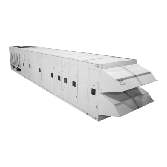
Packaged Rooftop Units & Outdoor Air Handling Units
Installation, Operation,
WARNING
FIRE OR EXPLOSION HAZARD
Failure to follow safety warnings
exactly could result in serious
injury, death or property damage.
Be sure to read and understand
the installation, operation and
service instructions in this manual.
Improper installation, adjustment,
alteration, service or maintenance
can cause serious injury, death or
property damage.
A copy of this IOM must be kept
with the unit.
& Maintenance
o Do not store gasoline or other flammable
vapors and liquids in the vicinity of this or any
other appliance
o WHAT TO DO IF YOU SMELL GAS
Do not try to light any appliance.
Do not touch any electrical switch; do not
use any phone in your building.
Leave the building immediately.
Immediately call your gas supplier from a
phone remote from the building. Follow the
gas supplier's instructions.
If you cannot reach your gas supplier, call
the fire department.
o Startup and service must be performed by a
Factory Trained Service Technician.
RZ SERIES
(45-240 tons)
WARNING
Advertisement
Table of Contents

Related Manuals for AAON RZ Series


Summary of Contents for AAON RZ Series
- Page 1 RZ SERIES (45-240 tons) Packaged Rooftop Units & Outdoor Air Handling Units Installation, Operation, & Maintenance WARNING WARNING o Do not store gasoline or other flammable FIRE OR EXPLOSION HAZARD vapors and liquids in the vicinity of this or any...
-
Page 3: Table Of Contents
Table of Contents Table of Contents AAON® RZ Series Features and Options Introduction ............. 7 Safety............................8 RZ Series Feature String Nomenclature ...................14 General Information .......................26 Codes and Ordinances......................27 Receiving Unit........................27 Storage ..........................28 Access Doors........................28 Wiring Diagrams ........................28 Installation ..........................28 Locating Units ........................28... - Page 4 Low Sound Condenser Fan EC Motor Startup..............52 Operation ..........................53 Packaged DX Cooling Operation..................53 Indirect Gas Heater Operation .....................53 Electric Heating Operation ....................53 Steam or Hot Water Preheating and Heating Operation ............53 Chilled Water or Non-Compressorized DX Cooling Operation ..........53 Maintenance ...........................54 Supply Fans........................54 Lubrication ........................
- Page 5 /hr) ............85 Table 25 - Propane (kBtu/hr) Maximum Piping Capacities ..............86 Table 26 - Piping Support Intervals....................87 Table 27 - Air Disinfection UV Information..................95 Table 28 - RZ Series Filter Sizes ....................96 Table 29 - Metal Mesh and HEPA Filter Sizes................97...
- Page 6 Figure 2 - RZ Series Unit Orientation...................29 Figure 3 - Base Rail Lifting Lug....................30 Figure 4 - 4 Point Lift RZ Series Air-Cooled Condenser Unit ............31 Figure 5 - 8 Point Lift RZ Series Air-Cooled Condenser Unit ............32 Figure 6 - Curb Mounting ......................33 Figure 7 - Curb Detail........................33...
-
Page 7: Aaon® Rz Series Features And Options Introduction
AAON® RZ Series Features and Options Introduction Energy Efficiency Installation and Maintenance Direct Drive Airfoil Plenum Supply Fans Clogged Filter Switch Variable Speed R-410A Scroll Color Coded Wiring Diagram Compressors Compressors in Isolated Compartment AAON Evaporative Condenser ... -
Page 8: Safety
Safety Attention must be paid to the following statements: NOTE - Notes are intended to clarify the unit installation, operation and maintenance. CAUTION - Caution statements are given to prevent actions that may result in equipment damage, property damage, or personal injury. WARNING - Warning statements are given to prevent actions that could result in equipment damage, property damage, personal injury or death. - Page 9 WARNING WARNING FIRE, EXPLOSION OR CARBON During installation, testing, servicing, MONOXIDE POISONING HAZARD and troubleshooting of the equipment it may be necessary to work with live Failure to replace proper controls electrical components. Only could result in fire, explosion or qualified licensed electrician...
- Page 10 WARNING WARNING GROUNDING REQUIRED UNIT HANDLING All field installed wiring must be To prevent injury or death, lifting completed by qualified personnel. equipment capacity must exceed unit Field installed wiring must comply with weight by an adequate safety factor. NEC/CEC, local and state electrical Always test-lift unit not more than 24 code requirements.
- Page 11 WARNING CAUTION WATER PRESSURE Do not clean DX refrigerant coils with hot water or steam. The use of hot Prior to connection of condensing water or steam on refrigerant coils will water supply, verify water pressure is cause high pressure inside the coil less than maximum pressure shown tubing and damage to the coil.
- Page 12 Never expose eyes or skin to UVC Failure of the condenser as a result of light from any source, as personal chemical corrosion is excluded from injury may result. Wear gloves, face coverage under AAON Inc. warranties shield/glasses (per ANSI Z87.1) and heat exchanger manufacturer’s warranties.
- Page 13 1. Startup and service must be performed by 8. Every unit has a unique equipment a Factory Trained Service Technician. nameplate with electrical, operational, unit clearance specifications. 2. Use only with type of the gas approved Always refer to the unit nameplate for for the furnace.
-
Page 14: Rz Series Feature String Nomenclature
RZ Series Feature String Nomenclature A - 0 0 0 0 0 : N 0 - A A K A Q - J 0 0 - B F T 0 M - 0 0 0 0 0 - Q F - A 0 A A... - Page 15 RZ Series Feature String Nomenclature : N 0 - A A K A Q - J 0 0 - B F T 0 M - 0 0 0 0 0 - Q F - A 0 A A 0 0 0 0 0...
- Page 16 RZ Series Feature String Nomenclature K A Q - J 0 0 - B F T 0 M - 0 0 0 0 0 - Q F - A 0 A A N 0 - A A RZ A - 145 - D...
- Page 17 RZ Series Feature String Nomenclature A K A Q - J 0 RZ A - 145 - D 0 - 3 - C A B 0 A - 0 0 0 0 0 : N 0 - A 0 - B F T 0 M - 0 0 0 0 0 - Q F - A 0 A A...
- Page 18 RZ Series Feature String Nomenclature 0 - 3 - C A B 0 A - 0 0 0 0 0 : N 0 - A A K A Q - J 0 0 - B F T 0 RZ A - 145 - D...
- Page 19 RZ Series Feature String Nomenclature 0 - 3 - C A B 0 A - 0 0 0 0 0 : N 0 - A A K A Q - J 0 0 - B F T 0 M - 0 0 0 0 0 -...
- Page 20 RZ Series Feature String Nomenclature 0 - 3 - C A B 0 A - 0 0 0 0 0 : N 0 - A A K A Q - J 0 0 - B F T 0 M - 0 0 0 0 0 -...
- Page 21 RZ Series Feature String Nomenclature 0 - 3 - C A B 0 A - 0 0 0 0 0 : N 0 - A A K A Q - J 0 0 - B F T 0 M - 0 0 0 0 0 - Q F - A 0 A...
- Page 22 RZ Series Feature String Nomenclature 0 - 3 - C A B 0 A - 0 0 0 0 0 : N 0 - A A K A Q - J 0 0 - B F T 0 M - 0 0 0 0 0 - Q F - A 0 A A...
- Page 23 RZ Series Feature String Nomenclature 0 - 3 - C A B 0 A - 0 0 0 0 0 : N 0 - A A K A Q - J 0 0 - B F T 0 M - 0 0 0 0 0 - Q F - A 0 A A...
- Page 24 RZ Series Feature String Nomenclature 0 - 3 - C A B 0 A - 0 0 0 0 0 : N 0 - A A K A Q - J 0 0 - B F T 0 M - 0 0 0 0 0 - Q F - A 0 A A...
- Page 25 G = Premium AAON Gray Paint Exterior + Interior Corrosion Protection + Shrink Wrap X = SPA + Premium AAON Gray Paint Exterior 30: MISCELLANEOUS OPTIONS Z = SPA + Premium AAON Gray Paint Exterior + 0 = None Interior Corrosion Protection A = High Condensate Level Switch...
-
Page 26: General Information
Models roofs. a. Certified as a forced air heating system with or without cooling. WARNING b. RZ Series hot water coils are designed for operation with no more than 180°F water at a 150 psig working pressure. Improper installation, adjustment, c. -
Page 27: Codes And Ordinances
Codes and Ordinances The RZ Series has been tested and certified WARNING by Intertek (ETL) to the following safety standards: Coils and sheet metal surfaces present sharp edges and care must ANSI Z21.47-2016/CSA 2.3-2016 be taken when working with this Gas-Fired Central Furnaces equipment. -
Page 28: Storage
Vent opening must not be blocked by snow. A minimum 12” curb must be used or the Installation vent outlet shall be greater than 12” off the AAON equipment is designed to be easily ground/roof. installed and serviced. Flue gas is dangerously hot and contains... -
Page 29: Curb Installation
CAUTION Outside Left Side All roofing work must be performed by competent roofing contractors Figure 2 - RZ Series Unit Orientation avoid any possible leakage. Table 2 - Evaporative Condenser Unit Clearances 45-240 ton CAUTION Location Clearance for 45-240 ton units Where the supply or warm air duct 100”... -
Page 30: Lifting The Unit
horizontal return discharge Lift the unit with the outside air hood in the applications, total height of mounting rail and downward shipping position. However, the unit base rail must be high enough so that unit may be lifted with the outside air hood in adequate condensate drain p-trap can be the open position. -
Page 31: Figure 4 - 4 Point Lift Rz Series Air-Cooled Condenser Unit
Figure 4 - 4 Point Lift RZ Series Air-Cooled Condenser Unit... -
Page 32: Figure 5 - 8 Point Lift Rz Series Air-Cooled Condenser Unit
Figure 5 - 8 Point Lift RZ Series Air-Cooled Condenser Unit Lifting slot locations are unit specific. Unit must be rigged at all marked lifting points. -
Page 33: Duct Connection
Duct Connection Figure 6 - Curb Mounting Figure 7 - Curb Detail Table 3 - Mounting Dimensions Tons 100” 96” 92” 97” 45-140 142” 138” 134” 139” 145-240 Figure 8 - Curb & Steel Mounting Rail with Dimensions... -
Page 34: Reassembling Split Units
6. Apply butyl caulking to all seams and Reassembling Split Units Some RZ Series units are built and shipped in perimeter of splice and to the perimeter of two separate sections. the roof splice cap against the roof of the unit. -
Page 35: Refrigeration Split Installation Procedure
Refrigeration Split Installation Procedure 2. Next remove the copper caps on each side If a given unit is too large to be shipped on by using a pipe cutter at the brazed joint one truck bed, the unit must be split. If the (Joint A and B). -
Page 36: Electrical Connection Of Split Units
Figure 12 - Air Hood Shown in the Open Position End Flashing Installation CAUTION On RZ Series D and E cabinet units which are 142” wide (RZ-145, 160, 180, 200, 220, 240) All wire terminations MUST BE made the cabinet width will overhang the trailer on before applying power to the unit. -
Page 37: Vestibule Exhaust Fan
Failure to attach and seal the end of unit with Motorized Exhaust & Rain Hood Narrow (100”) – The motorized exhaust the flashings will result in water leakage into the curb. damper and rain hood ships inside of the return air section. For proper unit operation, the motorized exhaust damper must be installed in the field. -
Page 38: Electrical
Electrical Verify the unit nameplate agrees with power supply. Connect power and control field wiring as shown on the unit specific wiring diagram provided laminated and attached to the door in the controls compartment. Table 4 - Nameplate Voltage Markings & Tolerances Acceptable Performance Nominal Operating Voltage Range... -
Page 39: Figure 16 - Power Block
Note: All units are factory wired for Three phase voltage imbalance will cause 208/230V, 460V, or 575V. If unit is to be motor overheating and premature failure. connected to a 208V supply, the transformer The maximum allowable imbalance is 2%. must be rewired to 208V service. -
Page 40: Variable Speed Compressors
Variable Speed Compressors Variable speed compressors with VFD speed control are standard on RZ Series units . Variable speed compressors must not be operated outside the factory determined turndown ratio or frequency range. The factory determined compressor VFD ranges are given in the following table. -
Page 41: Condensate Drain Piping
piping on these drain pans must be trapped to Condensate Drain Piping Unit is equipped with 2 or more condensate prevent pressure loss through the drain. drain pan connections. A drain line with p- trap must be installed on every drain Draw-Through Coils connection, with the p-trap not to exceed 6”... -
Page 42: Table 6 - Draw-Through Drain Trap Dimensions
CAUTION condensate drains must trapped individually before they are connected to a common line. Table 6 - Draw-Through Drain Trap Dimensions Draw-Through Drain Pan Pressure Trap Dimensions Negative Static (inches of water) (inch) (inch) Figure 18 - Blow-Through Drain Trap -0.50 1.50 0.75... -
Page 43: Startup
Startup (See back of the manual for startup form) WARNING Improper installation, adjustment, alteration, service or maintenance can cause property damage, personal injury or loss of life. Startup and service must be performed by a Figure 19 - Top Clip and Side Spring Factory Trained Service Technician. -
Page 44: Air Flow Monitoring
Supply, Return, and Exhaust Backward provided on the wheel. Once the band has Curved Fans RZ Series units are equipped with direct drive been inserted into the slots, it MUST BE backward curved fan assemblies that are secured by bending the tabs over from the... -
Page 45: Table 8 - Plenum Fan Set Screw Specifications
band ends together. Caution must be taken to Table 8 - Plenum Fan Set Screw Specifications SET SCREW TORQUE (IN- assure that the band is tightly installed and no DIAMETER LBS) damage, denting or alteration to the wheel or 1/4" blades occurs during the installation. -
Page 46: Back Draft Damper Setup
Back Draft Damper Setup The counter balance is shipped loose and may need to be installed during start-up on some applications. Not all applications will require the use of the counter balance on the back draft dampers. If the unit is equipped with back draft dampers on the supply fan, start the fans without the counter balance and observe the operation of the back draft... -
Page 47: Checking Liquid Sub-Cooling
reheat (dehumidification) mode to check for Checking Evaporator Superheat correct operation. Measure the temperature of the suction line close to the compressor. Units equipped with heat pump options must be charged in heating mode to get the proper Read gauge pressure at the suction line close charge. -
Page 48: Table 9 - Acceptable Fin & Tube Sub-Cooling And Superheat Temperatures
Table 9 - Acceptable Fin & Tube Sub-Cooling and Superheat Temperatures Air-Cooled Condenser Sub-Cooling 8-15°F / 2-4°F (HP)* Sub-Cooling with 8-15°F /2-6°F Hot Gas Reheat (HP)* Superheat 8-15°F Evaporative Condenser Sub-Cooling 6-10°F Sub-Cooling with 8-12°F Hot Gas Reheat Superheat 10-15°F Water-Cooled Condenser/ Water Source Heat Pump in Cooling Mode Sub-Cooling... -
Page 49: Adjusting Sub-Cooling And Superheat Temperatures
Adjusting Sub-cooling and Superheat CAUTION Temperatures The system is overcharged if the sub-cooling DO NOT OVERCHARGE! temperature is too high and the evaporator is fully loaded (low loads on the evaporator Refrigerant overcharging leads to result in increased sub-cooling) and the excess refrigerant in the condenser evaporator superheat... -
Page 50: Freeze Stat Startup
Table 11 - R-410A Refrigerant Temperature-Pressure Chart PSIG PSIG PSIG PSIG PSIG °F °F °F °F °F 78.3 134.7 213.7 321.0 463.2 80.0 137.2 217.1 325.6 469.3 81.8 139.7 220.6 330.2 475.4 83.6 142.2 224.1 334.9 481.6 85.4 144.8 227.7 339.6 487.8 87.2... -
Page 51: Suction Filter Removal Instructions
In an effort to help protect the compressors from contaminants during testing and startup, AAON factory installs pleated replaceable core suction line filters on the RZ Series. 5. Remove the pleated filter assembly Figure 27 - RPE-48-BD filter element One month after startup, remove the RPE-48- BD filter element for the lowest possible 6. -
Page 52: Vfd Controlled Condenser Fan Startup
Low Sound Condenser Fan EC Motor to 300 microns Startup 8. Open both shut-off valves AAON Condenser Head Pressure Module is used for variable speed control of the motor to maintain a head pressure. The motor must VFD Controlled Condenser Fan Startup When selected, the condenser fan VFD’s are... - Page 53 burners again. Should no flame be detected Operation after 3 tries, the ignition control will lock out Unit operations must be controlled with a unit the system. Power to the ignition control controller, never at the main power supply, must be cycled to reset the heater control. except for emergency or complete shutdown of the unit.
- Page 54 enough grease to purge the seals. DO NOT Maintenance OVER LUBRICATE. (See back of the manual for maintenance log) Recommended greases are: SHELL OIL - DOLIUM R At least once each year, a qualified service CHEVRON OIL - SRI No. 2 technician must check out the unit.
- Page 55 An elevated water temperature coils is required to maintain coating (not to exceed 130°F) will reduce surface warranty coverage for fin and tube and tension, increasing the ability to remove microchannel coils. AAON chlorides and dirt. E-Coated Coil Maintenance Record sheet.
- Page 56 The Enviro-Coil Cleaner: AAON PN: V82540 force of the water or air jet may bend the fin edges and increase airside GulfClean ™ Coil Cleaner ; AAON PN: pressure drop. Reduced unit...
- Page 57 These chemicals have been tested for performance and safety and are the only Rinse - Using pressurized potable water such chemicals that AAON will warrant as correct as a garden hose, (< 100 psi), rinse the coils for cleaning microchannel coils.
- Page 58 4. Rinse the coil with water as in step one. warranty. 5. Repeat as necessary. AAON testing has determined that unless a #2 Water Flush chemical has a neutral pH (6-8) it must not be This procedure can be used when the only used.
-
Page 59: Table 14 - Hot Water Coil Connection Sizes
Options WARNING (See back of the manual for maintenance log) Piping shall be in accordance with Heating Coils national and local codes. Pressure One or two row hot water and steam heating limiting devices, backflow preventers and preheating coils can be factory installed. and all other safety requirements are All valve controls for heating operation are the sole responsibility of the installing... -
Page 60: Table 16 - Chilled Water Coil Connection Sizes
Chilled Water Coil Four, six, or eight row chilled water cooling coils can be factory installed. All valve controls for cooling operation are field supplied and field installed. Chilled water coil connections are spun copper tube. Table 16 - Chilled Water Coil Connection Sizes Chilled Water Coil Model (RZA-) Coil Quantity*... - Page 61 time to clear any liquid accumulation out of units must be switched off during the heating the compressor before it is started. season. Always control the unit from the control Evaporator Coil panel, never at the main power supply, except WARNING for emergency or complete shutdown of the unit.
- Page 62 Connect the suction and liquid copper Remove the screws that attach the orifice to connections to the evaporator coil. Reinstall the condenser assembly. the expansion valve bulbs and/or the valve controller on the suction lines. With the wires disconnected and the screws removed, the fan, motor and orifice assembly Depending on the configuration, additional can be lifted off the unit.
-
Page 63: Figure 28 - Proper Unit Location
WARNING WARNING Batch-loading chemicals into the unit The evaporative condenser must be is NOT PERMITTED. The control thoroughly cleaned on a regular basis system must regulate the chemical to minimize the growth of bacteria, feed. including Legionella Pneumophila, to avoid the risk of sickness or death. Service personnel must wear proper Evaporative Condenser Location The recirculating water system contains... -
Page 64: Figure 30 - Temporary Drain Components
The unit is equipped with a Condenser Tube Inspection The coil is leak tested at 450 P.S.I.G. before water temperature controller which varies fan shipment. AAON will not be responsible for speed to maintain sump water temperature. - Page 65 If the water in the sump is below the low probe, it will not allow the condenser pump Condenser Fan Motors The direct-drive condenser motors on AAON or the sump heater to operate. It will activate evaporative condensers...
-
Page 66: Figure 31 - Water Makeup Valve
Never use Water Treatment System hydrochloric acid (muriatic acid) as it will All AAON evaporative condensers come corrode stainless steel. equipped with a water treatment system that must be maintained by a local water... - Page 67 system. This pressure switch is set to close at rotating element free and bearings fully 3 psi and open at 1 psi. functional. A sensor measures the water temperature in For long term storage, the pump must be the pump discharge line. If the sump water placed in a vertical position in a dry temperature exceeds 105°F, the cooling environment.
-
Page 68: Figure 32 - Evaporative Condenser Access Door
six (6) months thereafter. If a leak is found, 12. If the issues persists, repeat these steps as use the following steps to adjust the fit of the needed. door. This process will require at least two (2) people. Bearings - Lubrication Every 6 months or after a prolonged shut 1. - Page 69 Do not use wire brushes or any other desuperheater. Water usage of the AAON mechanical device on the copper tubing. evaporative condenser is approximately 22% Severe damage may result. Contact your...
- Page 70 less than evaporative condensers Evaporation Rate equipped with a desuperheater. 1,148,971 ( Btu hr ⁄ 525,000 ( Btu hr ⁄ ⁄ One method of calculating evaporation and = 2.19 gpm bleed in gallons per minute (gpm) is shown as follows: Assuming 4 cycles of concentration: Evaporation Rate Bleed Rate...
-
Page 71: Figure 33 - Aluminum Energy Recovery Wheel
Energy Recovery Units Some RZ Series units have been equipped performance. with an energy recovery wheel. AAON provides options for either an aluminum Controls energy recovery wheel or a polymer energy variety controls electrical recovery wheel. Follow the instructions for... -
Page 72: Figure 34 - Aluminum Erw Purge Sector Location
1. Monolith energy recovery wheel Aluminum Wheel Air Seals 2. Purge Sector Both non-contact sealing wheel 3. Profile peripheries and brush sealing middle beam 4. Motor are maintenance-free but their condition must 5. Brush Plate be checked every year. During the inspection, 6. - Page 73 If segmented drive belt becomes too loose it is necessary to pull out few segment modules (Fig. 10) of the belt and shorten the overall length to desired amount in order to achieve optimal tension. Correct tension should prevent ability to insert anything underneath the belt on the entire length between the belt and the wheel.
-
Page 74: Figure 35 - Polymer Energy Recovery Wheel
3. Connect the shortened belt ends by 1. Removable Segment inserting the protruding tongue through 2. Permanent Tension Belt the hole of the other half of the belt. 3. Pulley 4. Grab the second tongue and similarly 4. Embedded Segment Stiffeners insert it through the second hole –... - Page 75 Polymer Wheel Set Purge Angle When installed, the purge angle is factory set to 5 degrees. If a different angle is required, complete the following steps to adjust the purge: If it is necessary to adjust a purge seal to the face of the wheel, loosen the two or three screws along the bearing beam and adjust to the proper distance from the media surface.
- Page 76 pulled out from the cabinet to view the air permanently installed in a cabinet, access to seals. On larger units, the energy recovery both sides of the cassette must be provided. wheel may be accessible inside the walk-in cabinet. Polymer Wheel Orientation & Support The Energy Recovery Cassette may be A business card or two pieces of paper can be mounted in any orientation.
- Page 77 By hand, turn wheel clockwise (as viewed from the pulley side), to verify wheel turns freely through 360º rotation. Before applying power to drive motor, confirm wheel segments are fully engaged in wheel frame and segment retainers are completely fastened. (See Segment Installation Diagram).
-
Page 78: Figure 36 - Wheel Segment Removal Pattern
Polymer Wheel Air Seals Polymer Wheel Service Four adjustable diameter seals are provided CAUTION on each cassette to minimize transfer of air between the counter flowing airstreams. Disconnect electrical power before servicing energy recovery cassette. To adjust diameter seals, loosen diameter seal Always keep hands... - Page 79 Segment Installation 3. Holding segment by the two outer corners, press the segment towards the Segment Retainer center of the wheel and inwards against To install wheel segments follow the steps the spoke flanges. If hand pressure does below. Reverse procedure for segment not fully seat the segment, insert the flat removal.
- Page 80 While supporting weight of drive motor Loop the trailing end of the belt over the in one hand, loosen and remove (4) shaft (belt is partially through the mounting bolts. opening). Install replacement motor with hardware Reinstall the bearing onto the wheel shaft, kit supplied.
-
Page 81: Table 17 - Energy Recovery Wheel Cleaning Frequency
Energy Recovery Wheel General Cleaning Class contaminant Routine maintenance of the Energy Recovery concentration with inoffensive odor and Wheel includes periodic cleaning of the sensory irritation intensity. Energy Recovery Wheel as well as inspection Class 2 air has moderate contaminant Seals and Wheel Drive... - Page 82 ventilation of machine shop areas for CAUTION example, annual washing of energy transfer may be necessary to maintain latent transfer Disconnect electrical power before efficiency. Proper cleaning of the energy servicing energy recovery cassette. recovery wheel will restore latent Always keep hands away...
-
Page 83: Figure 37 - Defrost Timer
Soak in the solution until grease and tar deposits are loosened (Note: some staining of the desiccant may remain and is not harmful to performance). Before removing, rapidly run finger across surface of segment to separate polymer strips for better cleaning action. -
Page 84: Table 18 - Rz 45-140 Ton Electric Heating Capacities
Table 19 - RZ 145-240 ton Electric Heating Gas or Electric Heating Capacities The unit is designed to heat a given airflow. Model Electric Heat If this amount of air is greatly reduced, Option B3 Capacity approximately 1/3 during the heating season, kW (230V, the gas heat exchanger or electric heating coil 380V 460V,... -
Page 85: Table 22 - Rz 45-140 Ton Unit Gas Piping Connections
Unit Rating Sheet, which shipped. Above 2,000 ft the input rate is can be obtained from the AAON sales adjusted 4% for every 1,000 ft. representative. Table 24 - Natural Gas Maximum Piping Capacities (ft /hr) - Specific Gravity = 0.6, Supply Pressure ≤... -
Page 86: Table 25 - Propane (Kbtu/Hr) Maximum Piping Capacities
Table 25 - Propane (kBtu/hr) Maximum Piping Capacities Specific Gravity = 1.52, Supply Pressure = 11” w.c., Pressure Drop, 0.5” w.c. Length of Pipe Pipe Size 20 ft 50 ft. 100 ft. 150 ft. 200 ft. 1-1/4” 1495 1-1/2” 2295 1415 2”... -
Page 87: Table 26 - Piping Support Intervals
Piping shall not be strained or bent. AAON gas fired heat exchangers are designed to be non-condensing. These heat Table 26 - Piping Support Intervals exchangers are mounted downstream of the Support cooling coils. - Page 88 depending on national and local code DANGER requirements and the application of the final user. This condensate can stain the roof and Do not use open flame or other source it can cause rust in some cases on metal roofs. of ignition for leak testing.
-
Page 89: Figure 39 - Gas Heater Rain Hood
Installation of the gas heaters shall be adjusted to obtain an air temperature rise within the range specified on the rating plate. Rain Hoods Gas heating units include factory provided exterior rain hoods. The hoods are fastened in place with sheet metal screws. Higher heating capacity units will have two banks of gas fired heat exchanges (see Figure 39). - Page 90 Gas Heater Operating Instructions...
-
Page 91: Gas Heat Exchanger Removal
(see startup instructions). Turn the the unit. Cleaning shall only be done by a main electrical power on and set the controls qualified service agency and only after to the heating mode of operation. consultation with AAON service representative. The combustion ventilation motor will enable. -
Page 92: Phase And Brownout Protection Module
Attach the heat exchanger to the bulkhead DANGER using the holes around the perimeter. LEAK CHECK GAS PIPE Connect flex gas lines to the piping on the heat exchanger. If flexible gas piping in the The gas pipe in the unit must be unit must be replaced connectors cannot be checked for leaks before startup. - Page 93 Once the line voltages recover, the DPM will re-energize the output relay after the restart time delay. All settings and the last 4 faults are retained, even if there is a complete loss of power. DPM Setup Procedure With the supply voltage active to the module, you can setup all of the DPM’s settings without the line voltage connected.
- Page 94 Average Voltage Screen Screens VAvg Manufacturer’s Screen R-K Electronics DPM v0.0.00 Default – the default screen shows the real time voltage detected in each of the 3 phases: A-B B-C C-A Voltage Selection Screen (Vertical Format) Default = 460V, 3Ø 200, 1Ø;...
-
Page 95: Uv Lights
UV Lights WARNING Some units include UV lights for airstream disinfection. The UV fixture is installed directly downstream of cooling coil. Door UV LIGHTS interlock switches are provided with this option. UV lamps ship loose in the vestibule Never expose eyes or skin to UVC light from any source, as personal and require installation during startup. -
Page 96: Table 28 - Rz Series Filter Sizes
Table 28 - RZ Series Filter Sizes 4” Filters OR Cartridge Filters 32” Bag Filters Unit MERV 8 Filters Box A Box B Box C Box A Box B Box C Air Cooled Evaporative Condenser Condenser (24) 16x24 38,400 cfm... -
Page 97: Replacement Parts
* Note: When used in Final position the unit CFM limit will be the lesser between these and the corresponding MERV 8 Pre-Filters. Replacement Parts Always use AAON specified parts. Parts for AAON equipment may be obtained from you local AAON representative. When ordering parts, reference the unit serial number and part number. -
Page 98: Appendix A - Heat Exchanger Corrosion Resistance
Appendix A - Heat Exchanger Corrosion Resistance Corrosion Resistance of Copper and Stainless Steel in B razed Plate Heat Exchangers - Points to Measure and Check in a Water Analysis The resistance guide provides the corrosion resistance of stainless steel type AISI 316 and pure Copper (99.9%) in water, to a number of important chemical factors. - Page 99 Water Concentration Time Limits - AISI Copper Nickel Containing (mg/l or ppm) Analyze Before Alloy Alloy Total Hardness 4.0-8.5 No Limit (°dH) < 100 Nitrate (NO No Limit > 100 < 0.2 Iron (Fe) No Limit > 0.2 < 0.2 Aluminum (Al) No Limit >...
-
Page 100: Appendix B - Thermistor Temperature Vs. Resistance Values
Appendix B - Thermistor Temperature vs. Resistance Values Deg C Deg F Resistance (kOhms) Deg C Deg F Resistance (kOhms) 2889.6 15.07 2087.22 12.73 1522.20 10.79 1121.44 9.20 834.72 7.87 627.28 6.77 475.74 5.85 363.99 5.09 280.82 4.45 218.41 3.87 171.17 3.35 135.14... -
Page 101: Rz Series Startup Form
RZ Series Startup Form Date:______________ Job Name:_____________________________________________________________________ Job Address:____________________________________________________________________ ______________________________________________________________________________ Model Number:_________________________________________________________________ Serial Number:_____________________________________________ Tag:______________ Startup Contractor:______________________________________________________________ Contractor Address:________________________________________ Phone:____________ _________________________________________________________ Pre Startup Checklist Installing contractor must verify the following items: 1. Is there any visible shipping damage? 2. Is the unit level? 3. - Page 102 Supply Fan Assembly Alignment Check Rotation Nameplate Amps________ Number L1 Volts/Amps L2 Volts/Amps L3 Volts/Amps VFD Frequency________________ VAV Controls_________________ Energy Recovery Wheel Assembly Wheel(s) Spin Freely Check Rotation FLA____________ Number L1 Volts/Amps L2 Volts/Amps L3 Volts/Amps Power Return Assembly Alignment Check Rotation Nameplate Amps________ Number...
- Page 103 Outside Air/Economizer Dampers Operation Check Damper Actuator Type: Economizer Changeover Type and Operations: Damper Wiring Check Gears Check Unit Configuration Water-Cooled Condenser Air-Cooled Condenser No Water Leaks Evaporative Condenser Condenser Safety Check Water Flow ________GPM Water Inlet Temperature ________°F Water Outlet Temperature ________°F Compressors / DX Cooling Head Suction...
- Page 104 Ambient DB Temperature ________°F Ambient WB Temperature ________°F Coil Entering Air DB Temperature ________°F Coil Entering Air WB Temp ________°F Coil Leaving Air DB Temperature ________°F Coil Leaving Air WB Temp ________°F Refrigeration System 1 Saturated Line Pressure Sub-cooling Superheat Temperature Temperature Discharge...
- Page 105 Condenser Fans Alignment Check Rotation Nameplate Amps________ Number L1 Volts/Amps L2 Volts/Amps L3 Volts/Amps VFD Frequency________________ Evaporative Condenser Pumps Check Rotation Number L1 Volts/Amps L2 Volts/Amps L3 Volts/Amps Water/Glycol System 1. Has the entire system been flushed and pressure checked? 2.
- Page 106 Gas Heating Natural Gas Propane Purge Air from Lines Verify Pilot Spark Stage Manifold Pressure (w.c.) inlet Manifold Pressure (w.c.) outlet Electric Heating Stages__________ Limit Lockout Aux. Limit Lockout Stage Volts/Amps...
- Page 107 This log must be kept with the unit. It is the responsibility of the owner and/or maintenance/service contractor to document any service, repair or adjustments. AAON Service and Warranty Departments are available to advise and provide phone help for proper operation and replacement parts.
-
Page 108: Maintenance Log (E-Coated Coil)
Maintenance Log (E-Coated Coil) -
Page 109: Literature Change History
Updated the Condenser Fan removal instructions. Updated the Electric and Gas Heating Capacities tables. Updated the RZ 45-140 ton Unit Gas Piping Connections table. Updated the RZ Series Filter Sizes table. Added installation instruction for HEPA and metal mesh filters. -
Page 112: G074290 · Rev. A · 220113
Maintenance G074290 · Rev. A · 220113 It is the intent of AAON to provide accurate and current product information. However, in the interest of product improvement, AAON reserves the right to change pricing, specifications, and/or design of its product without notice, obligation, or liability.
Need help?
Do you have a question about the RZ Series and is the answer not in the manual?
Questions and answers