Table of Contents
Advertisement
AAON
HEATING • COOLING & COMBINATION
▲
!
WARNING
If the information in this manual is not followed
exactly, a fire or explosion may result causing
property damage, personal injury or loss of life.
FOR YOUR SAFETY
DO NOT STORE OR USE GASOLINE OR OTHER
FLAMMABLE VAPORS AND LIQUIDS IN THE
VICINITY OF THIS OR ANY OTHER APPLIANCE.
®
1
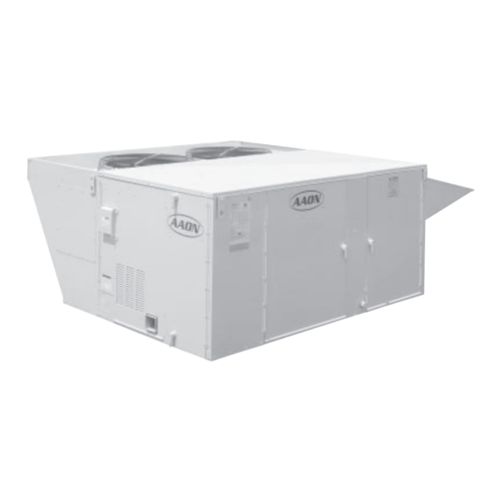
RM SERIES
ROOFTOP UNITS
INSTALLATION
INSTRUCTION
MANUAL
FOR YOUR SAFETY
WHAT TO DO IF YOU SMELL GAS
• EXTINGUISH ANY OPEN FLAME.
• DO NOT TOUCH ANY ELECTRICAL SWITCH.
• DO NOT TRY TO LIGHT ANY APPLIANCE.
• DO NOT USE ANY PHONE IN YOUR BUILDING.
• IMMEDIATELY CALL YOUR GAS SUPPLIER FROM A
NEIGHBOR'S PHONE.
FOLLOW THE GAS SUPPLIER'S INSTRUCTIONS.
• IF YOU CANNOT REACH YOUR GAS SUPPLIER,
CALL THE FIRE DEPARTMENT.
7-2003
Advertisement
Table of Contents

Related Manuals for AAON RM Series


Summary of Contents for AAON RM Series
- Page 1 ® AAON RM SERIES HEATING • COOLING & COMBINATION ROOFTOP UNITS INSTALLATION INSTRUCTION MANUAL 7-2003 ▲ FOR YOUR SAFETY WARNING WHAT TO DO IF YOU SMELL GAS • EXTINGUISH ANY OPEN FLAME. If the information in this manual is not followed exactly, a fire or explosion may result causing •...
-
Page 2: Table Of Contents
It is the intent of AAON, Inc. to provide accurate and current specification information. However, in the interest of product improvement, AAON, Inc. reserves the right to change pricing, specifications and/or design of it's products without notice, obligation or liablity. -
Page 3: General Description
GENERAL DESCRIPTION ▲ The units are designed as self-contained heating, cooling WARNING or combination units for outdoor installation only, using the refrigerant shown on the rating plate, chilled water, natural or propane gas, electric resistance, steam or hot Improper installation, adjustment, alteration, water. -
Page 4: Owner's Information
OWNER'S INFORMATION WARNING: Improper installation, adjustment, alter- WARNING ation, service, or maintenance can cause property dam- Failure to observe the following instructions will result in premature failure of your system, and possible void- age, personal injury or loss of life. Installation and service must be performed by a qualified installer, ser- ing of the warranty. -
Page 5: Heating / Cooling Systems
HEATING & COOLING SYSTEMS NORMAL OPERATION INSTALLATION IS TO BE ADJUSTED TO OBTAIN AN AIR TEMPERATURE RISE HEATING WITHIN THE RANGE SPECIFIED ON THE Set the thermostat system switch to "HEAT". RATING PLATE. Set the thermostat fan switch to "AUTO" or "ON". Set the thermostat temperature at the desired point. -
Page 6: Installation
INSTALLATION ▲ ▲ CAUTION WARNING If outside air is in contact with the bottom INSULATION MATERIALS MAY of the unit, the unit must have the bottom BE COMBUSTIBLE insulation option or be field insulated. GASKET DO NOT DRILL OR PUNCH HOLES IN BASE OF UNIT FROM INSIDE THE UNIT OR FROM BELOW TO ATTACH DUCTWORK. -
Page 7: Setting The Curb / Unit
INSTALLATION continued Prior to setting the unit onto the roof curb, be sure that AAON Rooftop units are designed for fast, easy installa- the gasket material has been applied to curb on all tion. The curb is mounted first and must be located so surfaces meeting with the unit. -
Page 8: Outside Air Hood
INSTALLATION continued ELECTRICAL OUTSIDE AIR HOOD Verify the unit data plate voltage agrees with the power CAUTION: Prior to unit operation, the outside air hood supply. Route power and control wiring through the must be opened as shown below: utility entry. Do not run power and signal wires in the same conduit. -
Page 9: Gas Piping
INSTALLATION continued GAS PIPING Utility Size gas piping to supply the unit with 6" to 10.5" water Access Heat column pressure for natural gas or 11" water column Exchanger pressure for propane when all gas consuming devices in Shut-off the building connected to the same gas system are Valve* operating. -
Page 10: Condensate Piping
INSTALLATION continued CONDENSATE PIPING WARNING AAON units are equipped with drain connections and 'P' traps are furnished with the equipment. All drain DO NOT USE OPEN FLAME OR OTHER SOURCE connections must be used and individually trapped to OF IGNITION FOR LEAK TESTING. -
Page 11: Gas Unit Lighting Instructions
GAS UNIT LIGHTING INSTRUCTIONS FOR YOUR SAFETY READ BEFORE OPERATING WARNING: IF YOU DO NOT FOLLOW THESE INSTRUCTIONS EXACTLY, A FIRE OR EXPLOSION MAY RESULT CAUSING PROPERTY DAMAGE, PERSONAL INJURY OR LOSS OF LIFE. This appliance does not have a pilot. It is equipped with an •... -
Page 12: Periodic Inspection Procedures
The cleaning should be done only by a qualified service agency after consultation with an AAON Service Representative. If the gas burners require cleaning, call an AAON Service Engineer at (918) 583-2266. HEAT EXCHANGER The necessity for cleaning the exchanger could indicate... - Page 13 PERIODIC INSPECTION PROCEDURES Continued COOLING HEATING • ELECTRIC 1. Main Power Switches are on and power is to the unit. 1. Set thermostat in the heat mode. 2. Set thermostat in cooling mode and place the "fan" 2. Set thermostat to call for heat to engage all electric switch to on.
-
Page 14: Service, Trouble Shooting & Maintenance
MODEL AND SERIAL NUMBER OF THE SPECIFIC TURN OFF POWER BEFORE ATTEMPTING TO UNIT TO CUSTOMER SERVICE TO ASSURE A COR- CLEAN BLOWER WHEEL. RECT DIAGNOSIS. AAON, Inc. Phone: 918-583-2266 Fax: 918-382-6364 Customer Service Department COMMON CAUSES OF REDUCED AIR FLOW DIRTY FILTERS - Filters must be inspected and replaced on a regular basis. -
Page 15: Filter Installation / Replacement
FILTER INSTALLATION / REPLACEMENT ▲ Before inspecting or replacing the filters, be sure the WARNING unit IS NOT operating. The filters are located in the filter access section of the unit. Open filter access door, and pull filters straight out to inspect. Inspect ALL Before attempting to perform any service filters each time. -
Page 16: Servicing
SERVICING TROUBLE POSSIBLE CAUSE ELECTRIC HEATING 1. Check power at line side of contactor(s). SYSTEM OFF 2. Thermostat not set for heating. 1. Overload relay tripped. 2. Heater Relay not energized. EVAPORATOR MOTOR WILL NOT RUN 3. Blower Contactor not energized. 4. - Page 17 SERVICING Continued TROUBLE POSSIBLE CAUSE STEAM AND HOT WATER HEATING 1. Check power at line side of contactor(s). SYSTEM OFF 2. Thermostat not set for heating. 1. Overload relay tripped. BLOWER MOTOR WILL NOT RUN 2. Heater Relay not energized. 3.
-
Page 18: Rooftop Unit Replacement Parts
COOLING unit to determine if adequate water is flowing. ROOFTOP UNIT REPLACEMENT PARTS Replacement parts for AAON equipment may be obtained from AAON. When ordering parts, always reference the unit model number, serial number and part number. AAON, Inc. Customer Service Department 2425 South Yukon Ave •... -
Page 19: Sequence Of Operations
SEQUENCE OF OPERATIONS GENERAL INFORMATION B. COOLING A. HEATING 1. Natural Gas 1. Packaged Units When the thermostat calls for heating, W1 makes R to When the thermostat calls for cooling from the space, 'Y1' makes 'R' to 'CC1' through the LPS (low pressure switch), the heat relay (HR). -
Page 20: Vav Systems
SEQUENCE OF OPERATIONS Continued II. VAV (Variable Air Volume) SYSTEMS B. Full modulating economizer, a full modulating power exhaust will control the amount of actual exhausted NOTE: VAV BOXES AND CONTROLS ARE air by means of a building sensing pressure control SUPPLIED BY OTHERS FOR FIELD INSTALLATION. -
Page 21: Compressor Checkout Procedure
COMPRESSOR CHECKOUT PROCEDURE CONTROL PANEL NOT SET FOR COOLING THERMOSTAT NOT CALLING FOR COOLING CHECK UNIT FUSES POWER TO AND WINDING UNIT LO PRESSURE SWITCH OPEN NO POWER TO HI PRESSURE SWITCH OPEN CONTACTOR NO POWER TO CHECK CIRCUIT BREAKER AT COMPRESSOR LOW AMBIENT LOCKOUT OPEN UNIT POWER DISTRIBUTION PANEL... -
Page 22: Ignition Control Checkout Procedure
IGNITION CONTROL CHECKOUT PROCEDURE WARNING: ALL SAFETY PRECAUTIONS MUST BE FOLLOWED WHEN EVALUATING THE IGNITION CONTROL SYSTEM ON GAS HEATING UNITS. CHECK GAS SUPPLY FOR OBSTRUCTIONS OR CLOSED VALVES IS GAS PRESSURE PER MANUFACTURE'S SPECIFICATIONS ? IS SPARK GAP LOCATED IN GAS STREAM ? SPARK IS PRESENT CHECK GAS VALVE... -
Page 23: Factory Start-Up Form
AAON , Inc. FACTORY START-UP FORM JOB NAME: DATE: ADDRESS: MODEL No: SERIAL No: CITY, STATE: START-UP CONTRACTOR: RTU No: START-UP CHECK LIST • GENERAL CHECKS Verify All Air Filters Are Installed: Inspect Unit For Damage: Inspect Economizer Damper Assembly:... - Page 24 RM SERIES ® AAON INSTALLATION INSTRUCTION MANUAL AAON, Inc. 2425 South Yukon Tulsa, Oklahoma 74107 ph: (918) 583-2266 • fax: (918) 583-6094 R15690 (7-03)
Need help?
Do you have a question about the RM Series and is the answer not in the manual?
Questions and answers