Sign In
Upload
Download
Table of Contents
Contents
Add to my manuals
Delete from my manuals
Share
URL of this page:
HTML Link:
Bookmark this page
Add
Manual will be automatically added to "My Manuals"
Print this page
×
Bookmark added
×
Added to my manuals
Manuals
Brands
Hypontech Manuals
Inverter
HMS-600W
User manual
Hypontech HMS-600W User Manual
Micro inverter
Hide thumbs
1
2
Table Of Contents
3
4
5
6
7
8
9
10
11
12
13
14
15
16
17
18
19
20
21
page
of
21
Go
/
21
Contents
Table of Contents
Troubleshooting
Bookmarks
Table of Contents
Table of Contents
Important Safety Instructions
Radio Interference Statement
Safety Requirements
Micro Inverter System Introduction
Working Mode
Work Mode
Unpacking
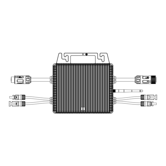
Product Overview
Installing
Installation Requirement
Mounting
Start up and Operation
Safety Check before Start up
Inverter LED Indicators
Disconnecting from Voltage Sources
Technical Parameters
Trouble Shooting
Accessories Summary
Advertisement
Quick Links
1
Technical Parameters
2
Trouble Shooting
Download this manual
Table of
Contents
Previous
Page
Next
Page
1
2
3
4
5
Advertisement
Table of Contents
Need help?
Do you have a question about the HMS-600W and is the answer not in the manual?
Ask a question
Questions and answers
Related Manuals for Hypontech HMS-600W
Inverter Hypontech HMS-800W User Manual
Micro inverter (21 pages)
Inverter Hypontech HPS Series User Manual
Single-phase grid-tied solar inverters (68 pages)
Inverter Hypontech HPS-3000DL User Manual
Single-phase grid-tied solar inverters (37 pages)
Inverter Hypontech HPK-1000 Series User Manual
Single-phase grid-tied solar inverters (32 pages)
Inverter Hypontech HPK-2000 Series User Manual
Single-phase grid-tied solar inverters (32 pages)
Inverter Hypontech HPK-2500 Series User Manual
Single-phase grid-tied solar inverters (32 pages)
Inverter Hypontech HPK-3000 Series User Manual
Single-phase grid-tied solar inverters (32 pages)
Inverter Hypontech HPT Series User Manual
3-phase grid-tied solar inverters (32 pages)
Inverter Hypontech HPT-30K Series User Manual
3-phase grid-tied solar inverters (35 pages)
Inverter Hypontech HPT-36K Series User Manual
3-phase grid-tied solar inverters (35 pages)
Inverter Hypontech HPT-50K Series User Manual
3-phase grid-tied solar inverters (35 pages)
Inverter Hypontech HHT-5000 Series User Manual
3-phase hybrid storage inverter (35 pages)
Inverter Hypontech HHT-12000 Series User Manual
3-phase hybrid storage inverter (35 pages)
Inverter Hypontech HPS 7000 Pro Series User Manual
Single-phase grid-tied solar inverters (24 pages)
Inverter Hypontech HES-3000 Series User Manual
Single-phase hybrid inverters (39 pages)
Inverter Hypontech HES-6000 Series User Manual
Single-phase hybrid inverters (39 pages)
This manual is also suitable for:
Hms-800w
Table of Contents
Save PDF
Print
Rename the bookmark
Delete bookmark?
Delete from my manuals?
Login
Sign In
OR
Sign in with Facebook
Sign in with Google
Upload manual
Upload from disk
Upload from URL


Need help?
Do you have a question about the HMS-600W and is the answer not in the manual?
Questions and answers