Table of Contents
Advertisement
Advertisement
Table of Contents

Subscribe to Our Youtube Channel
Related Manuals for Hypontech HPK-1000 Series


Summary of Contents for Hypontech HPK-1000 Series
- Page 2 HPK-1000/1500/2000/2500/3000 Series Single-Phase Grid-tied Solar Inverters USER MANUAL V1.00...
-
Page 3: Table Of Contents
CATALOGUE SYMBOLS ON THE LABEL .................. 4 SAFETY AND WARNINGS .................. 5 UNPACKING ......................6 3.1 Scope of Delivery ......................6 3.2 Product Overview ......................6 INSTALLING ......................8 4.1 Installation Requirement ....................8 4.2 Mounting Location ......................9 4.3 Mounting ......................... 10 4.4 Installing the PE cable .................... -
Page 4: Symbols On The Label
1. SYMBOLS ON THE LABEL DANGER, WARNING AND RECYCLABLE AND REUSABLE CAUTION HIGH VOLTAGE AVOID DAMP AND MOISTURE AVOID CONTACT HIGH TEMPERATURE SHIPMENT STACK LIMIT: 10 AVOID CONTACT DO NOT DISPOSE WITH CE MARKS HOUSEHOLD WASTE PROCEED OPERATIONS AFTER 5 MINUTES BREAKABLE ITEM DISCHARGE PLACE UPWARDS... -
Page 5: Safety And Warnings
2. SAFETY AND WARNINGS All persons who are responsible for mounting, installation, commissioning, maintenance, tests, and service of HYPONTECH inverter products must be suitably trained and qualified for corresponding operations. They MUST be experienced and have knowledge of operation safety and professional methods. All installation personnel must have knowledge of all applicable safety information, standards, directives, and regulations. -
Page 6: Unpacking
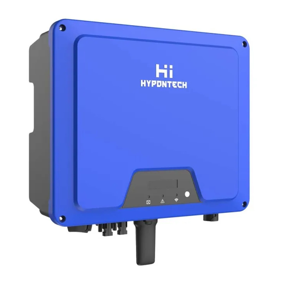
3. UNPACKING 3.1 Scope of Delivery Please inspect and check for completeness in the scope of delivery. Confirm with purchase order. INVERTER MOUNTING MOUNTING DC PLUGS AC CONNECTOR METER COMMUNICATI DOCUMENTS BRACKET ACCESSORIES (SEALED) CONNECTOR DATALOGGER (OPTIONAL) 1pair RS485/Wi-Fi/GPRS(optional)。 3.2 Product Overview The total size of HPK-1000/1500/2000/2500/3000 is 297(width) ×223(height) ×117(depth) mm. - Page 7 Mark Num. Component Description LCD&LED or LED Display and setting device at field DC Switch For switch on/off the inverter PV Terminal (s) Connected with PV Panel COM1: Wi-Fi/RS485/GPRS Alternative distant communication method COM2: METER For smart-meter AC Terminal Connected with AC Grid Secondary PE Terminal For Grounding Protection 7 HPS-1000/1500/2000/2500/3000 USER MANUAL...
-
Page 8: Installing
4. INSTALLING 4.1 Installation Requirement Please install the inverter(s) in places that can avoid inadvertent contact. Installation method, location and surface must be fitting for the inverter’s weight and dimensions. Please install the inverter in an accessible location for operation, future maintenance and service. -
Page 9: Mounting Location
4.2 Mounting Location DO NOT mount the inverter near any inflammable materials. DO NOT mount the inverter near any explosive materials. DO NOT mount the inverter on tilting surface over 15° backwards. Please mount the inverter on a vertical wall surface. DO NOT mount the inverter on any surfaces tilting forward or to either sides. -
Page 10: Mounting
4.3 Mounting Use the mounting bracket as a template and mark the drill holes. Drill 2 holes using a 10mm bit to 70mm depth. Fix the mounting bracket with the screws and expansion bolts packed in mounting accessories. Attach the inverter to the mounting bracket. Check both sides of the heat sink to ensure the inverter is stably attached. -
Page 11: Cable Specification
Information on grounding components: Object Description Housing M5 terminal lug with protective conductor M5×13 pan head screw PE Conductor cross-section: 4-6 mm² 4.5 Cable Specification 11 HPS-1000/1500/2000/2500/3000 USER MANUAL... -
Page 12: Commissioning
5. COMMISSIONING 5.1 Safety Instructions Measure the frequency and voltage of grid connection and make sure they follow the inverter’s grid connection specifications. An external circuit-breaker on the AC side (or a fuse) at 1.25*AC rated current is strongly recommended. Reliability of all earth connections must be tested and valid. -
Page 13: Dc Wire Assembly And Connection
5.3 DC Wire Assembly and Connection PV modules of the connected strings must be of: the same time, identical alignment and tilting angle. Before commissioning and connecting the PV arrays, the DC switch MUST be open. Parallel strings must have the same number of modules. It is mandatory to use the DC connectors within package for the connection of PV arrays. -
Page 14: Residual Current Protection
5.4 Residual Current Protection This product is equipped with residual current protection device internally, in accordance with IEC 60364-7-712. An external residual current protection device is not needed. If the local regulation demands otherwise, it is recommended to install a 30mA Type B residual current protection device. -
Page 15: Communication
Plug the Datalogger in and tighten. For user guidance and configuration of Datalogger, please refer to the corresponding HYPONTECH Wi-Fi Stick Guide manual, which is available in printed form inside Documents pack, or an online manual on HYPONTECH website at 6.1.2 RS485/Smart Meter Connection... -
Page 16: Output Power Control Via Smart Meter
6.2 Output Power Control via Smart Meter The inverter can control active power output via connecting smart meter, following is the system connection mode. Smart meter as above SDM230-Modbus connecting method and setting baud rate method for Modbus please refer to its user manual. 6.3 Demand Responsive Modes(DRMs)... -
Page 17: Auto Test (Only For Italian Market)
For user guidance and configuration of HiManager, please refer to the corresponding manual, available in Documents and HYPONTECH website. The inverter shall detect and initiate a response to all supported demand response commands , demand response modes are described as follows: 6.4 Auto Test (ONLY for Italian Market) - Page 18 of protection time. Inverter relay breaks off and reconnect to grid automatically according to CEI 0-21 requirement, Then the next test starts. Test order is 81>.S1(maximum over frequency), 81>.S2(maximum over frequency), 81<.S1(minimum under frequency), 81<.S2(minimum under frequency), 59.S1(maximum voltage over 10min), 59.S2(maximum over voltage), 27.S1(minimum under voltage), 27.S2(minimum under voltage).
-
Page 19: Start Up And Operation
7. START UP AND OPERATION 7.1 Safety Check Before Start Up Please check before switching on any voltage resources connected to the inverter and closing inverter’s DC switch: 1. Grid Voltage: Check the grid voltage at point of connection at the inverter complies with permitted range of the inverter. -
Page 20: Inverter Led Indicators
7.2 Inverter LED Indicators When the inverter operates, LED symbols on display have the following meanings: HPK-1000/1500/2000/2500/3000 USER MANUAL 20... -
Page 21: Display And Control Logics
7.3 Display and Control Logics When inverter starts up and operates, there is a control button beside LCD Display of the inverter. Please follow the logics listed below. System Loading Manufacturer Wait system loading Running Pac=xxxxxW short press E-Today=xx.xkWh Pac=xxxxxW short press E-Total=xxxxx.xkWh Pac=xxxxxW... -
Page 22: Disconnecting From Voltage Sources
8. DISCONNECTING FROM VOLTAGE SOURCES Before proceeding any operations on inverter, please disconnect the inverter from all voltage resources as described in this manual. Following these steps in described sequence are mandatory. Disconnect miniature circuit-breaker and prevent from unintentional reconnections. Open the DC switch and prevent the switch from closing unintentionally. -
Page 23: Technical Parameters
9. TECHNICAL PARAMETERS ( ) ( ) ( ) ( ) ( ) ( ) ( ) ( ) ( ) ( ) ( ) ( ) ( ) 23 HPS-1000/1500/2000/2500/3000 USER MANUAL... - Page 24 ( ) HPK-1000/1500/2000/2500/3000 USER MANUAL 24...
- Page 25 The power quality modes can be enabled or disabled via our monitoring APP or Web. Please refer to the “Safety Parameter Setting User Manual” on our website at https://www.hypontech.com/xiazai , or contact our servicer for more information. Please access the monitoring platform on www.hyponportal.com/signin...
-
Page 26: Trouble Shooting
If an external indication of earth fault alarm is required, please connect PV System to inverter monitoring app/portal. The monitoring platform will send email notification in the event of an Earth Fault. Please refer to Sector 6.1 and HYPONTECH WI-FI STICK GUIDE on how to setup your inverter communication function. - Page 27 1. Disconnect the inverter from the utility grid and the PV array, and reconnect it after LED turns off. 2. If the fault persists, measure the phase to phase voltage and The difference between INV phase to zero and zero to ground voltage with a multimeter to A faulty grid relay voltage and output voltage ensure that the voltage is normal and the zero to ground...
- Page 28 ⒈If it happens occasionally, it belongs to the short-time abnormality of the power grid, the inverter will return to normal operation after detecting that the power grid is normal, and there is no need to deal with it. Utility grid inverter detected grid voltage ⒉If it cannot be recovered for a long time, please confirm: disconnected...
- Page 29 ⒊If it cannot be recovered for a long time, please confirm: ①whether the AC circuit breaker is disconnected ②whether the AC terminal is in good connection ③whether the power supply line is normal ④ whether the safety regulation settings are normal DC component of the current exceeds 1A in Disconnect the inverter from the utility grid and the PV array, and...
- Page 30 Check the connection of DRM device. If the DRM device is DRM S0 Error DRM switch S0 fault connected normally while this fault occurs, please contact the service. HPK-1000/1500/2000/2500/3000 USER MANUAL 30...
-
Page 31: System Maintenance
11. SYSTEM MAINTENANCE For the inverter’s long-term performance, it is suggested to maintain your inverter regularly: NOTICE: HEAT SINK MIGHT INDUCE INJURY When the inverter is operating, the heat sink might exceed 60℃ • Please disconnect all electrical cables and connections. Wait for the inverter to cool down completely. -
Page 32: Restarts
12. RESTARTS When reconnecting the inverter for electrical power supply, please follow the commissioning procedures and safety instructions as described in Section 6 when applicable (e.g. DC Wires need to be reassembled). Please run safety checks as described in Section 7 before closing the DC Switch and starting up again, HPK-1000/1500/2000/2500/3000 USER MANUAL 32...
Need help?
Do you have a question about the HPK-1000 Series and is the answer not in the manual?
Questions and answers