Table of Contents
Advertisement
Quick Links
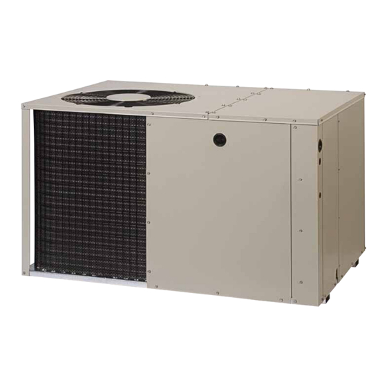
Q5RF / PPH2RF SERIES
INSTALLATION INSTRUCTIONS
Single Package Heat Pump - 2 Stage, R-410A
It is your responsibility to know this product better than your customer. This includes being
able to install the product according to strict safety guidelines and instructing the customer on
how to operate and maintain the equipment for the life of the product. Safety should always be
the deciding factor when installing this product and using common sense plays an important
role as well. Pay attention to all safety warnings and any other special notes highlighted in the
manual. Improper installation of the furnace or failure to follow safety warnings could result
in serious injury, death, or property damage.
These instructions are primarily intended to assist qualified individuals experienced in the
proper installation of this appliance. Some local codes require licensed installation/service
personnel for this type of equipment. Please read all instructions carefully before starting the
installation. Return these instructions to the customer's package for future reference.
DO NOT DESTROY. PLEASE READ CAREFULLY AND KEEP IN A SAFE PLACE FOR FUTURE REFERENCE.
IMPORTANT
ATTENTION INSTALLERS:
15 SEER
Advertisement
Table of Contents

Related Manuals for Nortek PPH2RF Series


Summary of Contents for Nortek PPH2RF Series
- Page 1 Q5RF / PPH2RF SERIES 15 SEER INSTALLATION INSTRUCTIONS Single Package Heat Pump - 2 Stage, R-410A IMPORTANT ATTENTION INSTALLERS: It is your responsibility to know this product better than your customer. This includes being able to install the product according to strict safety guidelines and instructing the customer on how to operate and maintain the equipment for the life of the product.
-
Page 2: Table Of Contents
Important Safety Information ........3 Startup & Adjustments ..........11 Pre - Start Checklist ..........11 Requirements & Codes ..........4 Start - Up Procedure ..........11 General Information ...........4 Air Circulation ............11 Before You Install this Unit .........4 System Heating ............11 Locating the Heat pump ...........4 System Cooling ............11 Air Duct System ............4 Short Cycle Protection .........11... -
Page 3: Important Safety Information
IMPORTANT SAFETY INFORMATION WARNING: Please read all instructions before servicing this equipment. Pay attention to all safety warnings and any other special PROPOSITION 65 WARNING: This product notes highlighted in the manual. Safety markings are contains fiberglass wool, a product known used frequently throughout this manual to designate a to the state of California to cause cancer. -
Page 4: Requirements & Codes
• Follow all precautions in the literature, on tags, and GENERAL INFORMATION on labels provided with the equipment. Read and Single packaged heat pumps are ready for easy and thoroughly understand the instructions provided with immediate installation and can be readily connected into the equipment prior to performing the installation and the high static duct system of a home. -
Page 5: Unconditioned Spaces
duct must be sufficiently large to conduct an adequate Installing Return & Supply Air Collars amount of air to each register. See Figure 3 (page 6). If the supply and return collars are supplied with the unit, • Duct work should be attached directly to the unit flanges they will be located in the supply duct. -
Page 6: Locating & Installing The Supply Dampers
MULTIPLE DUCT APPLICATION SINGLE DUCT APPLICATION Figure 3. Typical Duct Applications Condensate Drainage Locating & Installing the Supply Damper(s) A 3/4” condensate fitting extends out of the side of the unit as shown in Figure 4. The drain trap, shipped in the CAUTION: electrical compartment, must be installed to prevent water from collecting inside the unit. -
Page 7: Electrical Connections
• Connect the line-voltage leads to the terminals on the ELECTRICAL CONNECTIONS contactor inside the control compartment. Extend leads through power wiring hole (Figure 5). Connect L1 & L2 WARNING: directly to the contactor. • Use only copper wire for the line voltage power supply To avoid electric shock, personal injury, or death, to this unit. -
Page 8: Blower Speed
Blower Speed CAUTION: For optimum system performance and comfort, it may be necessary to change the factory speed setting. See Table To avoid personal injury or property damage, 1 below for factory settings. NOTE: This model has a High Efficiency ECM Motor with 5 speed taps. make certain that the motor leads cannot come into contact with any metal components of the WARNING:... -
Page 9: Demand Defrost Control
and 4 minutes, unless the coil temperature is above the selected terminate temperature. • The system can be manually forced into defrost mode at any time by shorting the TEST terminals on the demand defrost board together for more than 9 Bolt seconds. -
Page 10: Electric Heat Package
• Select the correct size heat package for the installation. Electric Heat Package (optional) • Follow installation instructions provided with each heater This heat pump is shipped without an auxiliary electric heat kit installed. If electric heat is desired, an accessory kit. -
Page 11: Startup & Adjustments
STARTUP & ADJUSTMENTS Short Cycle Protection The control circuit is equipped with a time-delay feature Pre-Start Checklist for protection against short cycling. With the system The following check list should be observed prior to operating in the cooling mode, gradually raise the starting the unit. -
Page 12: Charging The Unit In Heat Mode
• If the pressure measured in step 1 is less than the switch is designed to de-energize the system when very required liquid refrigerant pressure determined in high pressures occur during abnormal conditions. Under step 3, then there is too little charge in the system. normal conditions, the switch is closed. -
Page 13: Figures & Tables
FIgUreS & tABLeS top View Electric Heater Power Supply Power Supply Low Voltage Supply Control Blower Access Panel Side View Access 17.86 Panel 15.36 10.10 1" 3/4" NPT Drain Connection 1.38 18.01 3.2 5.29 12.13 Back (Duct) View 9.15 1" 3.15 9.04 17.50... -
Page 14: Refrigerant Charging Charts - Cooling Mode
REFRIGERANT CHARGING CHARTS - COOLING MODE X24K CHARGING CHART R em ove refrigerant w hen above c urve Add refrigerant w hen below c urve LIQUID TEMPERATURE (F) Figure 9. Charging Chart for 2 Ton Units X36K CHARGING CHART R em ove refrigerant w hen above c urve Add refrigerant w hen below c urve LIQUID TEMPERATURE (F) Figure 10. - Page 15 REFRIGERANT CHARGING CHARTS - COOLING MODE X48K CHARGING CHART R em ove refrigerant w hen above c urve Add refrigerant w hen below c urve LIQUID TEMPERATURE (F) Figure 11. Charging Chart for 4 Ton Units X60K COOLING CHARGING CHART R em ove refrigerant w hen above c urve Add refrigerant w hen below c urve LIQUID TEMPERATURE (F)
-
Page 16: Wiring Diagrams
WIRING DIAGRAMS Figure 13. Wiring Diagram - 2 & 3 Ton Units... - Page 17 Figure 14. Wiring Diagram - 4 & 5 Ton Units...
- Page 20 INSTALLATION / PERFORMANCE CHECK LIST ELECTRICAL SYSTEM: INSTALLATION ADDRESS: Electrical connections tight? CITY ________________ STATE _____________ Line voltage polarity correct? UNIT MODEL # _____________________________ Rated Voltage: ________________________ VOLTS UNIT SERIAL # _____________________________ L1-L2 Volts: __________________________ VOLTS Unit Installed Minimum Has the thermostat been clearances per Figure 1 calibrated? (page 4)?
Need help?
Do you have a question about the PPH2RF Series and is the answer not in the manual?
Questions and answers