Table of Contents
Advertisement
Quick Links
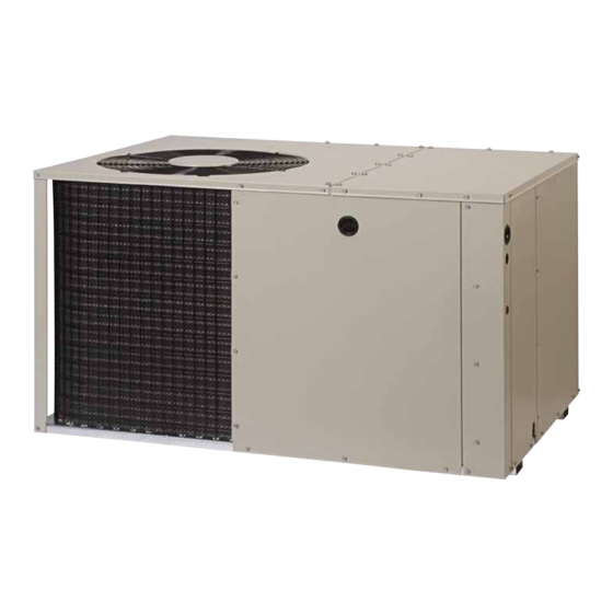
*Q7RD / PPH3RD SERIES
INSTALLATION INSTRUCTIONS
Single Package Heat Pump - Single Stage, R-410A
It is your responsibility to know this product better than your customer. This includes being
able to install the product according to strict safety guidelines and instructing the customer on
how to operate and maintain the equipment for the life of the product. Safety should always be
the deciding factor when installing this product and using common sense plays an important
role as well. Pay attention to all safety warnings and any other special notes highlighted in the
manual. Improper installation of the furnace or failure to follow safety warnings could result
in serious injury, death, or property damage.
These instructions are primarily intended to assist qualified individuals experienced in the
proper installation of this appliance. Some local codes require licensed installation/service
personnel for this type of equipment. Please read all instructions carefully before starting the
installation. Return these instructions to the customer's package for future reference.
DO NOT DESTROY. PLEASE READ CAREFULLY AND KEEP IN A SAFE PLACE FOR FUTURE REFERENCE.
IMPORTANT
ATTENTION INSTALLERS:
13 SEER
Advertisement
Table of Contents

Related Manuals for Nortek PPH3RD Series


Summary of Contents for Nortek PPH3RD Series
- Page 1 *Q7RD / PPH3RD SERIES 13 SEER INSTALLATION INSTRUCTIONS Single Package Heat Pump - Single Stage, R-410A IMPORTANT ATTENTION INSTALLERS: It is your responsibility to know this product better than your customer. This includes being able to install the product according to strict safety guidelines and instructing the customer on how to operate and maintain the equipment for the life of the product.
-
Page 2: Table Of Contents
TAbLE OF CONTENTS Important Safety Information ........3 Startup & Adjustments ..........11 Pre - Start Checklist ..........11 Requirements & Codes ..........4 Start - Up Procedure ..........11 General Information ...........4 Air Circulation ............11 Before You Install this Unit .........4 System Heating ............11 Locating the Heat pump ...........4 System Cooling ............11 Minimum Clearances ..........5... -
Page 3: Important Safety Information
IMPORTANT SAFETY INFORMATION WARNING: Please read all instructions before servicing this equipment. Pay attention to all safety warnings and any other special PROPOSITION 65 WARNING: This product notes highlighted in the manual. Safety markings are contains fiberglass wool, a product known used frequently throughout this manual to designate a to the state of California to cause cancer. -
Page 4: Requirements & Codes
GENERAL INFORMATION thoroughly understand the instructions provided with the equipment prior to performing the installation and Single packaged heat pumps are ready for easy and operational checkout of the equipment. immediate installation and can be readily connected • Use caution when handling this appliance or removing into the high static duct system of a home. -
Page 5: Minimum Clearances
Minimum Clearances The heat pump system will not cool or heat the home Minimum clearances MUST be maintained from adjacent if air is lost to the outside through leaks in the duct structures to provide room for proper servicing and air system. -
Page 6: Supply Duct
SINGLE DUCT APPLICATION MULTIPLE DUCT APPLICATION Figure 3. Typical Duct Applications Supply Duct • Homes with multiple supply ducts (or special 1. Assemble the collar by overlapping the two ends. applications), a Y fitting is available for dividing the NOTE: One end of the collar is slotted and the opposite supply air to different areas of the home for more efficient end has two small holes. -
Page 7: Locating & Installing The Supply Dampers
1. Thread the elbow provided with the unit into the drain connection until hand tight. 2. Connect the condensate tubing onto the fitting, forming a trap (Figure 6) near the drain connection. 3. Route the condensate tube from the trap to a suitable drain. -
Page 8: Overcurrent Protection
be capable of electrically de-energizing the outdoor unit. • Units are shipped from the factory wired for 240 volt See unit data label for proper incoming field wiring. Any transformer operation. For 208V operation, remove the other wiring methods must be acceptable to authority lead from the transformer terminal marked 240V and having jurisdiction. -
Page 9: Defrost Control Board
represent the time elapsed before defrosting cycle starts Normal Mode and they are dependent on the climate conditions of the To test normal defrost operation when the temperature is installation. A 30 minute setting would be recommended above 35° F, jumper R to DFT on the board and allow the in a moist climate such as Seattle Washington. -
Page 10: Blower Speed
blower Speed CAUTION: For optimum system performance and comfort, it may be necessary to change the factory speed setting. See Table To avoid personal injury or property damage, 2 for factory settings. make certain that the motor leads cannot come WARNING: into contact with any metal components of the unit. -
Page 11: Startup & Adjustments
STARTUP & ADjUSTMENTS Short Cycle Protection The control circuit is equipped with a time-delay feature Pre-Start Checklist for protection against short cycling. With the system The following check list should be observed prior to operating in the cooling mode, gradually raise the starting the unit. -
Page 12: Charging The Unit In Ac Mode With Outdoor Temperatures Above 65° F
Charging the Unit in AC Mode with Outdoor • Inspect the electrical connections for tightness at the Temperatures Above 65° F beginning of each heating and cooling season. Service 1. With the system operating at steady-state, measure as necessary. the suction and liquid refrigerant pressures (in psig) at the service valves. -
Page 13: Figures & Tables
FIGURES & TAbLES Top View Electric Heater Power Supply Power Supply Low Voltage Supply Control Blower Access Panel Access Side View 17.86 Panel 15.36 10.10 1" 3/4" NPT Drain Connection 1.38 18.01 3.2 5.29 12.13 Back (Duct) View 9.15 1" 3.15 9.04 17.50... -
Page 14: Charging Tables - Cooling Mode
REFRIGERANT CHARGING TAbLES - COOLING MODE Shaded boxes indicate flooded conditions. Rated design values are based on rated indoor air flow and 80 °F entering dry bulb. 1. Suction pressure will vary according to variations in indoor conditions. 2 All pressures are listed psig and all temperatures in °F 3. - Page 15 REFRIGERANT CHARGING TAbLES - COOLING MODE Shaded boxes indicate flooded conditions. Rated design values are based on rated indoor air flow and 80 °F entering dry bulb. 1. Suction pressure will vary according to variations in indoor conditions. 2 All pressures are listed psig and all temperatures in °F 3.
- Page 16 REFRIGERANT CHARGING TAbLES - COOLING MODE Shaded boxes indicate flooded conditions. Rated design values are based on rated indoor air flow and 80 °F entering dry bulb. 1. Suction pressure will vary according to variations in indoor conditions. 2 All pressures are listed psig and all temperatures in °F 3.
-
Page 20: Electrical Diagrams
ELECTRICAL DIAGRAMS Figure 9. Wiring Diagram - 2 & 2.5 Ton Models... - Page 21 Figure 10. Wiring Diagram - 3 Ton Models...
- Page 22 Figure 11. Wiring Diagram - 3.5 & 4 Ton Models...
- Page 23 INDOOR Outdoor DEFROST Thermostat T-STAT Green (Factory Option) BOARD SUB-BASE Brown Orange Accessory Brown wire not present when Heat Plug optional thermostat us used. Typical Wiring (Field Supplied) for 1-Stage Cool, 1 Stage Electric Heat INDOOR T-STAT SUB-BASE Green DEFROST BOARD Outdoor Thermostat (Factory Option)
-
Page 24: Installation / Performance Checklist
INSTALLATION / PERFORMANCE CHECK LIST REFRIGERATION SYSTEM INSTALLATION ADDRESS: Was unit given 24 hr warm up period for crankcase heaters (if applicable)? CITY ________________________ STATE ________________ UNIT MODEL # ________________________________________ Stage-1 Liquid Pressure (high side) ________________________ UNIT SERIAL # ________________________________________ Stage-1 Suction Pressure (low side) ________________________ Unit Installed Minimum clearances per Figure 1 (page 5)?
Need help?
Do you have a question about the PPH3RD Series and is the answer not in the manual?
Questions and answers