
Related Manuals for allen HDX Series


Summary of Contents for allen HDX Series
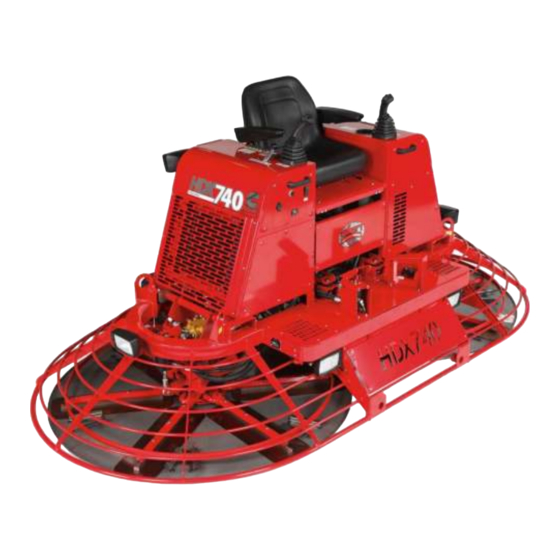
- Page 1 OPERATIONS-PARTS OPERATIONS-PARTS MANUAL MANUAL HDX740 Hydra-Drive Extreme (HDX) Series Riding Trowel 049831; 03/09...
- Page 2 This manual, or a copy of it, must be kept with the machine at all times. There is a manual storage container located on the machine for your convenience. 049831; 03/09...
- Page 3 No part of this manual may be reproduced or transmitted in any form or by any means, electronics or mechanical, for any purpose, without the express written permission of Allen Engineering Corporation (AEC). AEC assumes no responsibility or liability for any errors or inaccuracies that may appear in this manual.
-
Page 4: Limited Warranty
B. Hydraulics ..........One Year The above listed warranty periods are effective for Allen Machines with a first day of use by End User on April 1, 2007 or later. Warranty period begins on first day of use by End User. This first day of use is established by the date of a completed Allen Warranty Card or a Bill of Sale to the End User. -
Page 5: Table Of Contents
Table of Contents Sect No. Title Page Limited Warranty ..........ii Information Contained In This Manual . - Page 6 Table of Contents, continued Parts ........... .4-1 Factory Service Information .
-
Page 7: Information Contained In This Manual
Complete any warranty requirements as specified by the engine manufacturer in their instructions found inside the manual box located on the back of the riding trowel operator’s seat. Your engine and clutch is not manufactured by Allen Engineering Corporation (AEC) and there- fore is not covered under Allen Engineering Corporation, Inc warranty. -
Page 8: Dealer Information
Dealer Information Your Dealer has Allen Engineering Corporation trained mechanics and original Allen replacement parts. Always contact the Allen Dealer who sold you this machine for Allen Certified repairs and replacement parts. Place Allen Dealer information below for future reference... -
Page 9: Ordering Parts
Ordering Parts Section 4.0 contains illustrated parts lists for help in ordering replacement parts for your machine. Follow the instructions below when ordering parts to insure prompt and accurate delivery: All orders for service parts - include the serial number for the machine. Shipment will be delayed if this information is not available. - Page 10 Model Number - Serial Number Codes Manufacturer’s Codes: When ordering parts or requesting service information, you will always be asked to specify the model and serial numbers of the machine. The legends below specifically defines each significant character or group of characters of the Model Number and Serial Number codes. Model Number HDX 740 MODEL...
-
Page 11: Unit Identification
Unit Identification Unit Identification Plate Location: An identification plate listing the model number and the serial number is attached to each unit and is located on the rear lower left side of mainframe. Refer to Figure 1 for serial number and model number location. -
Page 12: Technical Specifications
Technical Specifications Measurements in this manual are in U.S. units and their customary metric units (i.e., metric units contained within brackets [mm]). The machine RIGHT-HAND and LEFT-HAND sides are deter- mined by sitting on machine (SOM) facing in the direction the machine will travel when going for- ward. - Page 13 Technical Specifications, continued CE MARKING Compliance: AEC hereby declares under our sole responsibility that the machine identified within this manual complies with the provisions in accordance with Machinery Directive 98/37/EC. AEC has applied the following normative documents: • 2000/14/EC; Noise Emission Of Outdoor Equipment Directive •...
-
Page 14: Engine Specifications
Engine Specifications Cummins Engine Information • Model ........A2300T •... -
Page 15: Machine Dimensional Specifications
Machine Dimensional Specifications All information, specifications, and illustrations on this page in this manual are subject to change without notice and are based on the latest information at the time of publication. 57.75” [1441 mm] HEIGHT 124” [3150 mm] LENGTH 63”... - Page 16 “normal ” circumstances. Values were obtained from all three axes of motion. The values shown represent the maximum RMS value from these measurements. Certified European testing was completed at the Allen Engineering Corporation facility. During the test the following data was collected and is on file at AEC under test number SND09-03001.
-
Page 17: Safety
SECTION 1 SAFETY Section 1 SAFETY 049831; 03/09... -
Page 18: State Regulations
State Regulations SECTION 1 SAFETY CALIFORNIA PROPOSITION 65 WARNING Engine exhaust from this product contains chemicals known to the State of California to cause cancer, birth defects and other reproductive harm. 049831; 03/09... - Page 19 Federal Regulations SECTION 1 SAFETY SILICOSIS WARNING Grinding/cutting/drilling of masonry, concrete, metal and other materials with silica in their composition may give off dust or mists containing crystalline silica. Silica is a basic component of sand, quartz, brick clay, granite and numerous other miner- als and rocks.
-
Page 20: General Safety Precautions
SECTION 1 General Safety Precautions SAFETY 1.1.1 Safety-Alert Signs This manual contains Safety-Alert Signs, as defined below, which must be followed to reduce the possibility of improper servi ce damage to the equipment or personal injury. Read and follow all Safety-Alert Signs included in this manual. NOTE defines an operating procedure, condition, etc. -
Page 21: Spark Arrestor Notice
SECTION 1 Spark Arrestor Notice SAFETY 1.2.1 Laws Pertaining to Spark Arrestors Some states require that in certain locations arrestors be used on internal combustion engines. A spark arrester is a device designed to prevent the discharge of spark or flames from the engine exhaust. It is often required when operating equipment on forested land to prevent the risk of fires. - Page 22 SECTION 1 Operating Safety SAFETY 1.3.1 Operating Safety Familiarity and proper training are required for the safe operation of this equipment! Equipment operated improperly or by untrained personnel can be dangerous! Read the operating instructions contained in both this manual and the engine manual and familiarize yourself with the location and proper use of all controls.
-
Page 23: Operating Safety
SECTION 1 1.3, continued Operating Safety SAFETY 1.3.13 ALWAYS close fuel valve on engines equipped with one when machine is not being operated. 1.3.14 ALWAYS store the equipment properly when it is not being used. Equipment should be stored in a clean, dry location out of the reach of children. 1.3.15 ALWAYS operate the machine with all safety devices and guards in place and in working order. -
Page 24: Engine Safety
SECTION 1 Engine Safety SAFETY 1.4.1 Engine Safety Internal combustion engines present special hazards during operation and fueling. Read and follow the warning instructions in the engine owner’s manual and the safety guidelines below. Failure to follow the warnings and safety guidelines could result in severe injury or death. 1.4.2 DO NOT run the machine indoors or in an enclosed area such as a deep trench unless adequate ventilation, through such items as exhaust fans or hoses, is... - Page 25 SECTION 1 Service Safety SAFETY 1.5.1 Service Safety Poorly maintained equipment can become a safety hazard! In order for the equipment to operate safely and properly over a long period of time, periodic maintenance and occasional repairs are necessary. 1.5.2 DO NOT attempt to clean or service the machine while it is running.
-
Page 26: Safety And Operation Labels
SECTION 1 Safety and Operation Labels SAFETY The safety and operation labels shown in this section are placed in important areas on the machine to draw attention to potential safety hazards and service information. Should any of these labels become unreadable or damaged, replacement labels can be odered from your dis- tributor. - Page 27 SECTION 1 1.6, continued Safety and Operation Labels SAFETY This label is a maintenance reminder to grease the thrust bearing daily. This will ensure that the life span of the bearings will be maintained at their optimal preformance level. This label cautions against allowing cleaning agents, surface treatments, or other foreign substances to contaminate drive components.
- Page 28 SECTION 1 1.6, continued Safety and Operation Labels SAFETY This label warns the operator of the potential hazard of servere burns from hot coolant if radiator is still hot and the radiator cap is removed before the coolant has had sufficient time to cool down.
-
Page 29: Operations
SECTION 2 OPERATIONS Section 2 OPERATIONS 049831; 02/09... - Page 30 This machine is built with user safety in mind. However, it can present hazards if improperly operated and serviced. Follow operating instructions carefully. If you have any questions about operating or servicing this equipment, please contact your Allen Engineering Dealer or AEC Customer Service at 800-643-0095 or 870-236-7751. 049831; 02/09...
-
Page 31: Description
The standard hydraulic drive system is designed to provide exceptional performance with low maintenance and trouble free use under some of the worst conditions. All Allen Engineering HDX740 trowels are equipped with a safety shutdown switch and a low oil warning light for added job safety and engine protection. -
Page 32: Before Starting Procedures
SECTION 2 Start Up Procedures OPERATIONS 2.2.1 Before Starting Procedures Before starting the riding trowel check for the following: Oil level in engine. Hydraulic oil level in the reservoir. Fuel level in fuel tank. Condition of riding trowel arms and blades. Verify that daily maintenance of grease points has been performed. -
Page 33: Start-Up Procedures
SECTION 2 2.2, continued Start Up Procedures OPERATIONS THROTTLE LIGHT SWITCH 12V ACC FIGURE 2.2.1 KEY SWITCH VIEW OF CONTROLS HOURMETER GLOW PLUG TEMPERATURE VOLTMETER FIGURE 2.2.2 VIEW OF CONTROLS MULTI GAUGE 049831; 02/09... - Page 34 2.3.1 Operating The Riding Trowel To utilize your Allen Engineering HDX740 Rider to its fullest capacity the machine should be driven in the direction the operator is facing. This will finish the widest possible area while giving the operator an excellent view of the slab surface about to be troweled.
-
Page 35: Stopping The Trowel
SECTION 2 2.3, continued Operating Instructions OPERATIONS With the operator in the seat, show him the functions of the joysticks [B] and [C] and how to start the machine. Refer to Figure 2.3.1. A hard level concrete slab with water on the surface is an ideal place for an operator to practice with the machine. -
Page 36: Steering The Trowel
SECTION 2 2.3, continued Operating Instructions OPERATIONS 2.3.3 Steering The Riding Trowel A slight "feathering motion" forward and backward with the left hand joystick is required to move the machine in a straight path to the left or right while operating the right hand joystick. -
Page 37: Pitch Adjustment
SECTION 2 2.3, continued Operating Instructions OPERATIONS 2.3.4 Pitch Adjustment Different pitch angles are needed as you work the different stages of the concrete. See the drawing below. When changing or setting pitch (angle of trowel blades), set the desired degree of pitch on the left side of the machine and then adjust the right side to match. -
Page 38: Cold Weather Startup Procedures
SECTION 2 2.3, continued Operating Instructions OPERATIONS 2.3.5 Cold Weather Startup Procedures When ambient temperatures are below 60°F (16°C) cold weather startup procedures must be followed before bringing machine into maximum engine RPM and rotor speed. If the procedure is not followed, damage could occur which will void the warranty. See below for startup procedure. -
Page 39: Service
SECTION 3 SERVICE Section 3 SERVICE 049831; 03/09... -
Page 40: Periodic Maintenance
SECTION 3 Periodic Maintenance SERVICE Periodic Maintenance Schedule The table below list basic trowel and engine maintenance. Refer to OEM engine manufacturer's Operation Manual for additional information on engine maintenance. A copy of the engine operator's manual was supplied with the machine when it was shipped. - Page 41 SECTION 3 Control Linkage Lubrication SERVICE The control linkage is equipped with several grease fitting to lubricate pivot points. Grease control linkage once a week or every 20 hours to prevent wear and ensure free movement and smooth response of control levers. Use a general purpose grease and add one to two shots of grease to each fitting.
- Page 42 SECTION 3 Lift Lever Adjustment SERVICE Lift Lever Adjustment Procedure Damage to and/or replacement of a trowel arm can change the adjustment of the lift lever. This can unbalance the trowel arms and cause the riding trowel to wobble during operation. To operate smoothly the lift lever on all trowel arms must be adjusted the same to ensure that the riding trowel is balanced correctly.
-
Page 43: Lift Lever Adjustment
SECTION 3 3.3, continued Lift Lever Adjustment SERVICE STABILIZER RING TROWEL ARM BLADE FIGURE 3.3.1 PRESSURE PLATE LOCATION SPIDER BOSS FIGURE 3.3.2 FASTENER HARDWARE REMOVAL 049831; 03/09... - Page 44 SECTION 3 Transporting Trowel SERVICE Transporting Trowel Procedures Optional dolly jacks are available for short moves or to aid in servicing the trowel. Install dolly jacks as follows: Inspect dolly jack for serviceability and damage. Place riding trowel on firm level ground. Insert the front dolly jack [J] fully into the holes in the mainframe of the riding trowel.
-
Page 45: Transporting Trowel
SECTION 3 3.4, continued Transporting Trowel SERVICE The dolly jack lifting system is designed for short moves and to aid in servicing the trowel. It is not a substitute for a towing system or trailer. An optional lifting bridle [N] is available and recommended for lifting the trowel. - Page 46 SECTION 3 3.4, continued Transporting Trowel SERVICE FIGURE 3.4.4 LIFTING HOOK LOCATION 049831; 03/09...
-
Page 47: Battery Jump Start
SECTION 3 Battery Jump Start SERVICE Battery Jump Start Procedures Occasionally it may be necessary to jump start a weak battery. If jump starting is necessary the following procedure is recommended to prevent starter damage, battery damage, and personal injury. Jump starting a battery incorrectly can cause the battery to explode resulting in severe personal injury or death. - Page 48 SECTION 3 3.5, continued Battery Jump Start SERVICE BATTERY FIGURE 3.5.1 BATTERY LOCATION 3-10 049831; 03/09...
-
Page 49: Parts
SECTION 4 PARTS Section 4 PARTS 049831; 03/09... -
Page 50: Factory Service Information
SECTION 4 Factory Service Information PARTS This section contains the illustrated drawings and parts list for help in identifying and/or ordering replacement parts for your machine. Follow the instructions in the front section of this manual “Ordering Parts” when ordering replacement parts to insure prompt and accurate delivery. The Right Hand (RH) and/or Left Hand (LH) orientations are defined from the operator’s view of sitting on machine (SOM). -
Page 51: Replacement Part Procedure
SECTION 4 Replacement Parts Procedures PARTS We recommend Allen quality replacement parts, available from the AEC Customer Service Department or your nearest AEC Dealer. Part numbers are subject to change without notice. Part numbers might be different outside of the United States of America. Use part numbers listed in the applicable parts list table when you place your order. - Page 52 4.1 Illustration SECTION 4 Seat Frame Unit - 049554 PARTS 049831; 03/09...
- Page 53 SECTION 4 4.1 Parts List Seat Frame Unit PARTS ITEM PART # DESCRIPTION 010007 FSTN, HHCS 1/4-20 X 2 010081 FSTN, FW 1/4 020542 NUT, 1/4-20 ZINC STOVER 032125 SWITCH, ROCKER #91B2184 034876 DECAL, LIGHTS 036881 LIGHT ASSEMBLY 038979 DECAL, FWD-REV/LT-RT 038980 DECAL, FWD-REV 039048...
- Page 54 4.1 Illustration SECTION 4 Seat Frame Unit (cont’d) PARTS 049831; 03/09...
- Page 55 SECTION 4 4.1 Parts List Seat Frame Unit (cont’d) PARTS ITEM PART # DESCRIPTION 049558 COVER, REAR LH HDX740 049559 COVER, REAR RH TOP HDX740 049560 COVER, REAR RH BOTTOM HDX740 049579 AIR CLEANER 60HP CUMMINS 049580 MOUNTING BAND FOR HDX740 AIR CLEANER 049582 1/2"-2"...
- Page 56 SECTION 4 4.1 Illustration Seat Frame Unit (cont’d) PARTS 049831; 03/09...
- Page 57 4.1 Parts List SECTION 4 Seat Frame Unit (cont’d) PARTS ITEM PART # DESCRIPTION 010007 FSTN, HHCS 1/4-20 X 2 010081 FSTN, FW 1/4 020542 NUT, 1/4-20 ZINC STOVER 032125 SWITCH, ROCKER #91B2184 034876 DECAL, LIGHTS 036881 LIGHT ASSEMBLY 038979 DECAL, FWD-REV/LT-RT 038980 DECAL, FWD-REV...
- Page 58 SECTION 4 4.2 Illustration Main Frame Assembly - 049740 PARTS 4-10 049831; 03/09...
- Page 59 4.2 Parts List SECTION 4 Main Frame Assembly PARTS ITEM PART # DESCRIPTION 010001 FSTN, HHCS 1/4-20 X 1/2 GR 5 010035 FSTN, HHCS 3/8-16 X 3/4 010036 FSTN, HHCS 3/8-16 X 1 010089 FSTN, LW 1/4 010091 FSTN, LW 3/8 010098 FSTN, NUT HEX 1/4-20 010568...
- Page 60 SECTION 4 4.2 Illustration Main Frame Assembly (cont’d) PARTS 4-12 049831; 03/09...
- Page 61 048676 PLUG, HOLLOW SBR RUBBER 048680 CAP, VENTED W/ GAUGE X1 048737 FTG., 6407-16-16-NWO 048937 DECAL, MFG BY ALLEN ENGR 049501 WELD, MAIN FRAME HDX740 049531 COVER, FRONT FOR HDX740 049738 BEARING ASSEMBLY FOR HDX740 WITH WHITE D9 MOTORS 049806...
- Page 62 SECTION 4 4.3 Illustration Power Unit Assembly - 049590 PARTS Replacement Filter Kit - 049853 049849 - Fuel Filter - Cummins 049850 - Oil Filter - Cummins 049851 - Primary Air - Cummins 043920 - Aux Fuel Filter - AEC 4-14 049831;...
-
Page 63: Power Unit Assembly
4.3 Parts List SECTION 4 Power Unit Assembly PARTS ITEM PART # DESCRIPTION 010001 FSTN, HHCS 1/4-20 X 1/2 GR 5 010002 FSTN, HHCS 1/4-20 X 3/4 010082 FSTN, FW 5/16 010093 FSTN, LW 1/2 011490 FSTN, FW HARDENED 1/2 020542 FSTN, NUT STOVER LOCK 1/4-20 021072... - Page 64 SECTION 4 4.4 Illustration PARTS Left Rotor Assembly - 049596 4-16 049831; 03/09...
-
Page 65: Left Rotor Assembly
SECTION 4 4.4 Parts List PARTS Left Rotor Assembly ITEM PART # DESCRIPTION 010024 FSTN, HHCS 5/16-18 X 2 GR 5 010036 FSTN, HHCS 3/8-16 X 1 010068 FSTN, HHCS 1/2-13 X 1 1/4 GR 8 010069 FSTN, HHCS 1/2-13 X 1-1/2 010090 FSTN, LW 5/16 010091... - Page 66 4.5 Illustration SECTION 4 Right Rotor Assembly - 049595 PARTS 4-18 049831; 03/09...
-
Page 67: Right Rotor Assembly
SECTION 4 4.5 Parts List PARTS Right Rotor Assembly ITEM PART # DESCRIPTION 010024 FSTN, HHCS 5/16-18 X 2 GR 5 010068 FSTN, HHCS 1/2-13 X 1-1/4 GR 8 010069 FSTN, HHCS 1/2-13 X 1-1/2 010090 FSTN, LW 5/16 010093 FSTN, LW 1/2 010106 FSTN, NUT HEX 1/2-13... - Page 68 4.6 Illustration and Parts List SECTION 4 LH Spider Assembly - 049538 PARTS ITEM PART # DESCRIPTION 010050 FSTN, NUT HEX JAM 1/2-13 015682 FSTN, LW EXT STAR 3/8 015683 FSTN, 3/8-16 X 7/8 DOG CAP SCREW 015684 FSTN, NUT HEX JAM 3/8-16 015686 FSTN, SQHSS 3/8-16 X 1 024755...
- Page 69 SECTION 4 4.7 Illustration and Parts List PARTS RH Spider Assembly - 049539 ITEM PART # DESCRIPTION 010050 FSTN, NUT HEX JAM 1/2-13 015682 FSTN, LW EXT STAR 3/8 015683 FSTN, 3/8-16 X 7/8 DOG CAP SCREW 015684 FSTN, NUT HEX JAM 3/8-16 015686 FSTN, SQHSS 3/8-16 X 1 024755...
- Page 70 SECTION 4 4.8 Illustration PARTS Hydraulic Schematic 4-22 049831; 03/09...
-
Page 71: Hydraulic Schematic
4.8 Illustration SECTION 4 Hydraulic Schematic PARTS 049831; 03/09 4-23... - Page 72 4.9 Illustration SECTION 4 PARTS Electrical Harness Schematic 4-24 049831; 03/09...
-
Page 73: Electrical Harness Schematic
4.9 Illustration SECTION 4 Electrical Harness Schematic PARTS 049831; 03/09 4-25... -
Page 74: Tools
SECTION 4 4.10 Tools and Accessories PARTS 040041 - LIFT BRIDLE 016863 - TROWEL ARM JIG 046443 - COMPODISK, 59-1/4" OD X 1" 047153 - PAN, FLAT 59-1/4" CLIP-ON (SHOWN) 047125 - PAN FLAT 59-1/4" SAFETY CATCH 049858 - HDX740 SPIDER PULLER 4-26 049831;... -
Page 75: 4.11 Dolly Jack Assembly
4.11 Dolly Jack Assembly SECTION 4 048770 PARTS ITEM PART # DESCRIPTION 010091 FSTN, LW 3/8 010133 PIN, Ø3/16 X 2 ZP STL COTTER 026775 FSTN, HHCS 3/8-16 X 2 GR 8 039094 SPACER, SP DOLLY JACK OUTSIDE 039095 WHEEL, SP DOLLY JACK 048423 BUMPER, RUBBER F/ HDX DOLLY JACK 048769... - Page 76 SECTION 4 Notes PARTS 4-28 049831; 03/09...
- Page 77 INTENTIONALLY BLANK 049831; 03/09...
- Page 78 YOUR TOTAL SOURCE FOR CONCRETE EQUIPMENT 049831; 03/09...
Need help?
Do you have a question about the HDX Series and is the answer not in the manual?
Questions and answers