Table of Contents
Advertisement
Quick Links
Advertisement
Table of Contents

Related Manuals for Supermicro MBB-CMM-6


Summary of Contents for Supermicro MBB-CMM-6
- Page 1 MBB-CMM-6 Blade Module Board USER'S GUIDE Revision 1.0...
- Page 2 This product, including software and documentation, is the property of Supermicro and/or its licensors, and is supplied only under a license. Any use or reproduction of this product is not allowed, except as expressly permitted by the terms of said license.
- Page 3 About this User's guide This user's guide is written for system integrators, IT technicians, and knowledgeable end users. It provides information for the installation and use of the MBB-CMM-6 blade module board upon which the Supermicro MBM-CMM-6 Chassis Management Module (CMM) is built.
- Page 4 Super Micro Computer, Inc. 980 Rock Ave. San Jose, CA 95131 U.S.A. Tel: +1 (408) 503-8000 Fax: +1 (408) 503-8008 Email: Marketing@supermicro.com (General Information) Sales-USA@supermicro.com (Sales Inquiry: Non-Government) Government_Sales-USA@supermicro.com (Sales Inquiry: Government) Support@supermicro.com (Technical Support) RMA@supermicro.com (RMA Support) Website: www.supermicro.com Europe Address: Super Micro Computer B.V.
-
Page 5: Table Of Contents
Preface Table of Contents Chapter 1 Introduction 1.1 The MBB-CMM-6 Blade Module Board Overview ...............6 1.2 MBB-CMM-6 Board Quick Reference ..................9 Quick Reference Table ......................10 1.3 MBB-CMM-6 Blade Module Board Hardware Features .............11 1.4 MicroBlade Chassis Management Module Diagram ............13 1.5 Chassis Management Module (CMM) Firmware Features ..........14... -
Page 6: Chapter 1 Introduction
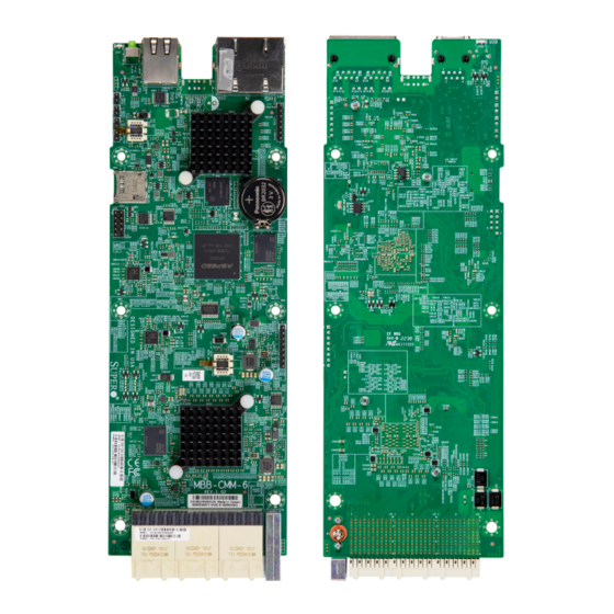
Congratulations on purchasing your blade module board from an industry leader. The MBB-CMM-6 module board is designed to provide you with the highest standards in quality and performance for use in a Supermicro proprietary blade server module as a part of an integrated system management solution. - Page 7 Chapter 1: Introduction MBB-CMM6 Module Board Image Front Side Rear Side Note: All graphics shown in this user's guide were based upon the latest PCB revision available at the time of publication of this user's guide. The module that you received may or may not look exactly the same as the graphics shown in the user's guide.
- Page 8 LED6 Console1 LED2 PWR LED Serial Console USB 0/1 Ethernet LAN Port BMC SPI Flash JSD1 BMC EMMC MBB-CMM-6-Rear Side CMOS CLEAR Battery LED3 LED5 BMC Status LED PHY Acti v i t y LED (Baseboard Manage- ment Controller) MBB-CMM-6 REV:1.03...
-
Page 9: Mbb-Cmm-6 Board Quick Reference
Chapter 1: Introduction 1.2 MBB-CMM-6 Board Quick Reference Front Side Rear Side UID LED (LED2) Console1 USB 0/1 LAN Port UID LED Power LED (LED6) USB1 JLAN1 LED6 Console1 LED2 PWR LED Serial Console USB 0/1 Ethernet LAN Port BMC SPI Flash... -
Page 10: Quick Reference Table
Use only the correct type of onboard CMOS battery as specified by the manufacturer. Do not install the onboard battery upside down to avoid a possible explosion. • For BMC configuration instructions, please refer to the Embedded BMC Configuration User's Guide available at http://www.supermicro.com/support/manuals/. -
Page 11: Mbb-Cmm-6 Blade Module Board Hardware Features
Chapter 1: Introduction 1.3 MBB-CMM-6 Blade Module Board Hardware Features MBB-CMM-6 Blade Module Board Features Chips Supported • Supports ASpeed AST2600 Baseboard Management Controller (BMC) with ROT (Root of Trust) 2.0 • Supports Microsemi switching chip (VSC7546) BMC Connection •... - Page 12 Super MBB-CMM6 Blade Module Board User's Guide I/O Ports/Connections • One 1 GbE Ethernet LAN port (JLAN1) • One dedicated BMC port with support of RJ45 • One USB connector (JUSB1) with support of two USB 3.0 ports (USB 0/1) •...
-
Page 13: Microblade Chassis Management Module Diagram
Chapter 1: Introduction 1.4 MicroBlade Chassis Management Module Diagram P0V9 P1V0 U618 P3V3_STBY_BMC P12V_IN HotSwap P12V BMC Voltage MAX15090B 12V_STBY_IN RTCVDD P1V2_ P1V0_ P1V8_ P2V5_ P3V3 LAN Voltage DS1340 P2V5 P1V8 P1V2 P3V3_LAN GPIOs (PRSNT#) I2C1-7, 14 SCL/SDA U611 PW1-2 SCL/SDA RS232 UART Aspeed... -
Page 14: Chassis Management Module (Cmm) Firmware Features
Utilities: SMCIPMITOOL for CMM and IPMICFG for BMC & RedFish compliant w/KVM over LAN or IP • Supports RMCP & RMCP+ Protocols, LAN Alert-SNMP Trap, Event Log Note: For more firmware information, please refer to the CMM_BMC Manual posted on our website under the link: http://www.supermicro.com/. - Page 15 Media ISO Image Mount Software/Firmware Tool Support • Supermicro Server Manager (SSM): A comprehensive solution to manage and maintain Supermicro servers in an IT datacenter from a single console view. • Supermicro Update Manager (SUM): In-band and out-of-band command line tool, supporting firmware (BIOS, BMC etc.) image updates and configurations.
- Page 16 Note 1: For more firmware information, please refer to the CMM_BMC Manual posted on our website under the link: http://www.supermicro.com/. Note 2: The browsers provided in the table above have been verified to be CMM- compatible. Refer to the next section (Section 1.6) for network connection and login...
-
Page 17: Network Connection/Login
1.6 Network Connection/LogIn To use the web-based system management utility provided by the MBM-CMM-6 blade module which is built upon the MBB-CMM-6 board, please follow the instructions below. Supported Browsers The following browsers are verified to be compatible with the CMM web-based system management utility. -
Page 18: Setting Up The Chassis Management Module Utility Via Serial Console
Super MBB-CMM6 Blade Module Board User's Guide program. To change default address settings, please refer to Chapter 4 of the CMM_BMC manual posted on our website under the link: http://www.supermicro.com/. Manufacturer IP Address Defaults Default Description Default IP Address https://192.168.100.100 Default Gateway Address 0.0.0.0... - Page 19 Chapter 1: Introduction Command List There are a list of CMM commands that you can use to set up your Chassis Management Module (CMM) utility settings. For example, by using the CMM "SET" command in conjunction with the "APPLY SETTING" command, you can configure (set) a new CMM setting, save it, and then apply the changes to the CMM utility as shown below.
-
Page 20: Chapter 2 Installation
Super MBB-CMM6 Blade Module Board User's Guide Chapter 2 Installation 2.1 Static-Sensitive Devices Electrostatic Discharge (ESD) can damage electronic com ponents. To avoid damaging your blade module or blade module board, it is important to handle it very carefully. The following measures are generally sufficient to protect your equipment from ESD. -
Page 21: Cmm Blade Module Board Installation
CLEAR Battery LED3 LED5 BMC Status LED PHY Acti v i t y LED (Baseboard Manage- ment Controller) MBB-CMM-6 REV:1.03 PHY Acti v i t y LED LED4 BMC SPI Flash LAN Swi t ch Status LED LED1 Switch Midplane Connector... - Page 22 Super MBB-CMM6 Blade Module Board User's Guide Installing the Blade module Board 1. Install the I/O shield into the back of the chassis, if applicable. 2. Locate the mounting holes on the blade module board. See the previous page for the location.
-
Page 23: Connectors And Headers
Midplane Connectors Three Midplane connectors are located at J565/J566/J567 on the MBB-CMM-6 module board. These Midplane connectors provide connections between the components installed on the blade module and the blade server in which the MBB-CMM-6 module is installed. USB1 JLAN1... - Page 24 During a system cold boot or BMC Reset, LED3 will turn green (solid) on. Please refer to the BMC User's Guide at http://www. supermicro.com for more information on BMC settings. UID LED (LED2)
- Page 25 Chapter 2: Installation COM/Serial Port A COM (communication) port that provides serial link interface is located on the MBB-CMM-6 blade module board. Refer to the layout below for the location of the COM/Serial Port. Console Port A Console port (Console1) located next to the USB ports support UART connections. See the layout below for the location of Consle1.
- Page 26 CLEAR Battery LED3 LED5 BMC Status LED PHY Acti v i t y LED (Baseboard Manage- ment Controller) MBB-CMM-6 REV:1.03 PHY Acti v i t y LED LED4 BMC SPI Flash LAN Swi t ch Status LED LED1 Switch Midplane Connector...
- Page 27 Chapter 2: Installation SD Card Connector (JSD1) A Secure Digital (SD) connector, located at JSD1 on the MBB-CMM-6, supports SD devices, including standard memory cards. Refer to the layout below for the location of JSD1. Universal Serial Bus (USB) Ports and Headers A Type A USB header, located at JUSB1, supports two USB 3.0 connections (USB Port0/...
-
Page 28: Jumper Settings
Super MBB-CMM6 Blade Module Board User's Guide 2.4 Jumper Settings How Jumpers Work To modify the operation of the blade module board, jumpers can be used to choose between optional settings. Jumpers create shorts between two pins to change the function of the connector. - Page 29 CLEAR Battery LED3 LED5 BMC Status LED PHY Acti v i t y LED (Baseboard Manage- ment Controller) MBB-CMM-6 REV:1.03 PHY Acti v i t y LED LED4 BMC SPI Flash LAN Swi t ch Status LED LED1 Switch Midplane Connector...
-
Page 30: Led Indicators
2.5 LED Indicators LAN LEDs An 1GbE Ethernet LAN port is located at JLAN1 on the rear I/O side of the MBB-CMM-6 board. This Ethernet LAN port has two LEDs. The yellow LED on the right side indicates activity, and the amber LED on the left side indicates the speed of the connections. Refer to the tables below for more information. - Page 31 Chapter 2: Installation PHY Activity LEDs Two Intel PHY LED indicators are located at LED4 and LED5 on the MBB-CMM-6. These LEDs indicate the status of PHY connections and the activity status of the Ethernet LAN connection. Refer to the table below for more information.
- Page 32 CLEAR Battery LED3 LED5 BMC Status LED PHY Acti v i t y LED (Baseboard Manage- ment Controller) MBB-CMM-6 REV:1.03 PHY Acti v i t y LED LED4 BMC SPI Flash LAN Swi t ch Status LED LED1 Switch Midplane Connector...
-
Page 33: Chapter 3 Troubleshooting
Chapter 3: Troubleshooting Chapter 3 Troubleshooting 3.1 Troubleshooting Procedures Use the following procedures to troubleshoot your system. If you have followed all of the procedures below and still need assistance, refer to the ‘Technical Support Procedures’ and/ or ‘Returning Merchandise for Service’ section(s) in this chapter. Always disconnect the AC power cord before adding, changing or installing any non hot-swap hardware components. - Page 34 Super MBB-CMM6 Blade Module Board User's Guide No Video 1. If the power is on, but you do not have video, remove all add-on cards and cables from the blade module and the blade server. 2. Remove all memory modules and turn on your server (if the alarm is on, check the specs of memory modules, reset the memory, or try a different one).
-
Page 35: Technical Support Procedures
Before contacting Technical Support, please take the following steps. Also, please note that as a system manufacturer, Supermicro also sells computers through its channels, so it is best to first check with your distributor or reseller for troubleshooting services. They should know of any possible problems with the specific system configuration that was sold to you. -
Page 36: Battery Removal And Installation
Super MBB-CMM6 Blade Module Board User's Guide 3.3 Battery Removal and Installation Battery Removal To remove the onboard battery, follow the steps below: 1. Power off your server and unplug your power cable. 2. Locate the onboard battery as shown below. 3. -
Page 37: Returning Merchandise For Service
For faster service, you can also request a RMA authorization online (http://www.supermicro. com/RmaForm/). This warranty only covers normal consumer use and does not cover damages incurred in shipping or from failure due to the alternation, misuse, abuse or improper maintenance of products. -
Page 38: Appendix A Standardized Warning Statements
The following statements are industry standard warnings, provided to warn the user of situations where a potential bodily injury may occur. Should you have questions or experience difficulty, contact Supermicro's Technical Support department for assistance. Only certified technicians should attempt to install or configure components. - Page 39 Appendix A: Standardized Warning Statements Attention Danger d'explosion si la pile n'est pas remplacée correctement. Ne la remplacer que par une pile de type semblable ou équivalent, recommandée par le fabricant. Jeter les piles usagées conformément aux instructions du fabricant. ¡Advertencia! Existe peligro de explosión si la batería se reemplaza de manera incorrecta.
- Page 40 Super MBB-CMM6 Blade Module Board User's Guide Product Disposal Warning! Ultimate disposal of this product should be handled according to all national laws and regulations. 製品の廃棄 この製品を廃棄処分する場合、 国の関係する全ての法律 ・ 条例に従い処理する必要があります。 警告 本产品的废弃处理应根据所有国家的法律和规章进行。 警告 本產品的廢棄處理應根據所有國家的法律和規章進行。 Warnung Die Entsorgung dieses Produkts sollte gemäß allen Bestimmungen und Gesetzen des Landes erfolgen.
Need help?
Do you have a question about the MBB-CMM-6 and is the answer not in the manual?
Questions and answers