Table of Contents
Advertisement
Quick Links
Inductive Proximity Sensor
Variable Sensing Distance and
Differential Travel Allow a Wide Range
of Applications
Various Sensing Heads available in outer diame-
ters from 2.0 to 40 mm.
Operation and stability indicators (LED) in Amplifier
Unit allow easy monitoring of stable operation.
Amplifier Unit has wide-ranging operating voltages,
10 to 30 VDC or 90 to 264 VAC.
Small differences in size, distance, and materials
can be detected.
Ordering Information
AC 2-wire Models
Size
Shield
Sensing
di t
distance
2.0 dia.
Un-
0.5 mm
shielded
(see
note1)
Shielded
3.5 dia.
0.8 mm
1 mm
3.8 dia.
M5
5.4 dia.
M8
1.5 mm
M12
2 mm
M18
5 mm
M30
10 mm
40 dia.
Un-
20 mm
shielded
Note: 1. The E2C-CR5B cannot be flush-mounted in metal even though the E2C-CR5B is of a shielded construction.
2. Use the E2C-WH4AF in combination with the S3D8 Sensor Controller
3. The E2C-JCA4P is an Amplifier Unit with self-diagnostic output for DIN track mounting.
g
Maxi-
Sensor
mum
H
Head
d
operat-
ing dis-
tance
E2C-
1.2 mm
E2C-
CR5B
AK4A
1.8 mm
E2C-
CR8A
2 mm
E2C-
CR8B
E2C-
X1A
E2C-
C1A
3 mm
E2C-
X1R5A
5 mm
E2C-
X2A
10 mm
E2C-
X5A
18 mm
E2C-
X10A
50 mm
E2C-
C20MA
Amplifier Unit
Multi-function
AC
DC
DC
(PNP,
(NPN)
NPN)
E2C-
---
AM4A
E2C-
JC
JCA4
E2C
Single-function
DC
DC
DC
(PNP,
(NPN)
(PNP)
NPN)
---
E2C-
E2C-
GE4B
GF4B
E2C-
E2C-
E2C-
WH4AF
G
GE4A
GF4A
G
(see
(
note 2)
E2C-
E2C-
WH4A
---
---
---
Self-
diag-
nostic
function
DC
(NPN)
---
E2C-
JC
JCA4P
(see
(
note 3)
1
Advertisement
Table of Contents

Subscribe to Our Youtube Channel
Related Manuals for Omron E2C


Summary of Contents for Omron E2C
- Page 1 C20MA Note: 1. The E2C-CR5B cannot be flush-mounted in metal even though the E2C-CR5B is of a shielded construction. 2. Use the E2C-WH4AF in combination with the S3D8 Sensor Controller 3. The E2C-JCA4P is an Amplifier Unit with self-diagnostic output for DIN track mounting.
-
Page 2: Specifications
Specifications Sensor Heads Model E2C-CR5B E2C-CR8A E2C-X1A E2C- E2C-X2A E2C-X5A E2C-X10A E2C- E2C-CR5B E2C-C1A X1R5A C20MA Sensing object Magnetic metals (Refer to Engineering Data for non-magnetic metals.) Standard sensing Iron: 5 x 5 x Iron: 5 x 5 Iron: 5 x 5... - Page 3 Cable Lengths vs. Amplifier Unit and Sensor Head Combinations Amplifier Sensor Head U it Unit E2C- E2C- E2C- E2C-X1A E2C-C1A E2C- E2C-X2A E2C-X5A E2C- E2C- CR5B CR8A CR8B X1R5A X10A C20MA E2C-GE4B 3 m only E2C-GF4B E2C-GE4A 3 m only...
- Page 4 (E2C-JC4AP: Approx. 80 g) Note: 1. A power supply with full-wave rectification with an average output of 24 VDC"10% can be used with all E2C Amplifier Units except the E2C-GE4j. 2. The sensing distance adjustable range indicates the sensing range of the E2C Amplifier Unit in satisfactory operation with Sensors.
-
Page 5: Operation
Voltage output from E2C-GE4j will be available if the operation selector Orange (Yellow) is set to NC. When using voltage output, be sure to reset the E2C-GE4j Self-diagnostic after the E2C-GE4j is turned on, at which moment the E2C-GE4j gen-... -
Page 6: Self-Diagnostic Function
Self-diagnostic Function The output transistor of self-diagnostic output will turn on instantly if the E2C detects one of the following events. 1. Sensor wire burnout 2. The operation indicator is ON for 0.3 s or more while the sensing object is at 93% to 100% of the sensing distance. This will occur if the sensing object is in the wrong position, for example. -
Page 7: Sensitivity Adjustment
0.96 for the E2C-X2A. Sensitivity Adjustment 1. Initial Adjustment After the E2C Amplifier Unit is turned on, adjust the following Sensor according to the status of each indicator without a sensing object. E2C-Gj4j Single-function Model E2C-JC4A Multi-function Model E2C-WH4A(F) Multi-function Model... - Page 8 80% maximum of the set distance. A caution label is provided with the E2C Amplifier Unit. After completing sensitivity adjustment, affix the caution label over the adjuster hole of the cover to prevent mis-operation of the E2C Amplifier Unit.
-
Page 9: Engineering Data
(variable): 0.2 to 0.5 mm (variable): 0.2 to 1 mm (variable): 0.16 to 0.8 mm Y (mm) Y (mm) E2C-CR8j 2-dia. Sensing Head Y (mm) E2C-X1A Sensing Head Sensing Head E2C-C1A Sensing Head E2EC-X1R5A E2EC-X2A E2EC-X5A Sensing object: Iron Sensing object: Iron... - Page 10 Sensing Distance vs. Sensing Object (Typical) E2EC-CR5B E2C-CR8j E2C-X1A/E2C-C1A Iron Iron Iron Stainless steel (SUS304) Brass Aluminum Size of sensing object ! (mm) Size of sensing object ! (mm) Size of sensing object ! (mm) E2EC-X1R5A E2EC-X2A E2EC-X5A Iron Iron...
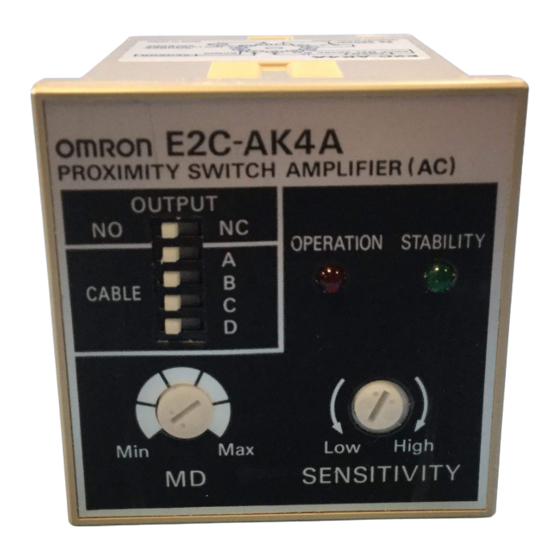
- Page 11 Operation indicator The 40-ms OFF-delay timer will be enabled if the OFF-delay Sensitivity adjuster terminals are short-circuited. Operation selector E2C-JC4AP Self-diagnostic Output Model Settings Mounting screw The output transistor is ON when the sensing object is detected. The output transistor is ON when the...
- Page 12 1 m different from the actual length. Except for the E2C-C20MA, this method can protect the sensors from mutual interference. 2. Set all the pins of the switch to the left if the E2C-CR5B is used in combination with the E2C-AM4A or E2C-AK4A.
- Page 13 E2C-CR8A/-CR8B 3.5 dia. (see note) 3.5 dia. 2.5-dia. coaxial cable; standard length: 3 m Note: The diameter of the coaxial cable is 3.8 mm for the E2C-CR8B. E2C-X1A 2.5-dia. coaxial cable; standard length: 3 m E2C-C1A 5.4 dia. 2.5-dia. coaxial cable; standard length: 3 m E2C-X1R5A 2.5-dia.
- Page 14 E2C-X5A 4.1-dia. coaxial cable; standard length: 3 m E2C-X10A 5.5-dia. coaxial cable; standard length: 3 m E2C-C20MA 40 dia. 5.5-dia. coaxial cable; standard length: 3 m Mounting Hole Dimensions Model F (mm) +0.3 E2C-CR5B dia. +0.3 E2C-CR8A dia. E2C-CR8B +0.3 dia.
- Page 15 Connector to S3D-jjF Two, M4 screw holes To be mounted on DIN track E2C-JC4A Location of caution label (provided with Four, M2.6 terminals E2C-JC4A) (see note) Mounting Bracket (Provided with E2C-JC4A) Vinyl-insulated round cable with three conductors, 4 dia. (0.2 mm x 3 (18/0.12));...
-
Page 16: Installation
1. Paste the caution label after the sensitivity adjustment of the E2C-JC4AP to prevent mis-operation. 2. The mounting bracket will not be required if the E2C-JC4AP is mounted to DIN tracks. 3. Vinyl-insulated round cable with four conductors, 4.5 dia. (18/0.12); standard length: 2 m... -
Page 17: Load Connection
DC solid-state circuitry 50 min. 30 V nin. CED: Remarks The C-MOS IC or TTL can be connected to the E2C-GE4j through the interface and DC solid-state circuitry as shown in the above circuit diagram. E2C-GC4A Load/Model E2C-GC4A Direct load driving... - Page 18 E2C-WH4A(F) The E2C-WH4A(F) has NPN and PNP open collector outputs. Therefore, there is a degree of freedom in load types and power supply polarity. DC solid-state load Load Direct load driving Voltage load (logic load) Current-absorbing load Relay Solenoid Programmable Controller...
- Page 19 Amplifier Track- Unit Unit mounting mounting Solder Screw Socket Socket (see Socket terminal terminal note) E2C-AK4A P2CF1-11 PL11 P3GA-11 E2C-AM4A P2CF-08 PL08 P3G-08 E2C-Gj4j PYF08A PY08 PYF08M Note: Track-mounted socket can be used as a front-connecting socket. Track-mounted Socket/Front-connecting Socket...
- Page 20 Back-connecting Socket P3GA-11 Front View Terminal Arrangement 27 dia. P3G-08 Mounting Dimensions Embedding Adapter (Front view) Y92F-30 (l = 45) Y92F-71 (l = 55) 27 dia. Terminal Arrangement Embedding Adapter Y92F-70 Two, 4.5-dia. adapter mounting holes R0.5 max. 52 to 53 65 to 66 PY08 Eight 3 x 1.2 elliptic holes...
- Page 21 PL08 Terminal Arrangement Mounting Holes Two 3.5 dia. or two M3 socket-mounting holes 31 dia. Two 2 dia. holes hole 50.5 max. 30 dia. (Bottom view) 35 max. Approx. 20.5 PYF08M 3 dia. 3.5 dia. hole 40 max. 3.5 dia. hole or M3 44.5 max.
- Page 22 Mounting Effects of Surrounding Metal Do not apply excessive torque to the mounting nuts of the E2C-X or When mounting the E2C within a metal panel, ensure that the clear- E2C-C20MA. Be sure to tighten each nut with a toothed washer.
- Page 23 2. Press the rear part of the E2C-JC4AP onto the Mounting the E2C-JC4A. Bracket or DIN track. 2. Slide and insert the protruding part of the E2C-JC4A into the hole of the mounting bracket. Rear part 3. Mount the E2C-JC4A with the mounting screw.
- Page 24 Y92F-30 2. If the Y92F-70 or Y92F-71 Mounting Adapter is used, just insert the E2C-Aj4A into the square panel hole. If the panel coating is too thick and the hooks do not snap on, spread out Wiring the Self-diagnostic Output...
Need help?
Do you have a question about the E2C and is the answer not in the manual?
Questions and answers