Table of Contents
Advertisement
Quick Links
Advertisement
Table of Contents

Related Manuals for KERN KKP V40


Summary of Contents for KERN KKP V40
- Page 1 KERN & Sohn GmbH Ziegelei 1 Phone: +49-[0]7433- 9933-0 D-72336 Balingen Fax: +49-[0]7433-9933-149 E-Mail: info@kern-sohn.com Internet: www.kern-sohn.com Installation instructions weighing bridge KERN KKP V40 Version 1.1 03/2018 KKP_V40-IA-e-1811...
-
Page 2: Table Of Contents
KERN KKP V40 Version 1.1 03/2018 Installation instructions weighing bridge Contents General hints ....................3 Technical data ....................3 Basic instructions ..................3 Documentation ........................... 3 Proper use ..........................3 Improper Use ..........................4 Warranty ............................. 4 Monitoring of Test Resources ....................4 Basic Safety Precautions ................ -
Page 3: General Hints
3.1 Documentation These installation instructions contain all data necessary for placing and commissioning the weighing bridges KERN KKP V40M. In combination with a display unit, described below as weighing system, for operation configuration, please refer to the operating instructions of the display unit. -
Page 4: Improper Use
Information is available on KERN’s home page (www.kern-sohn.com with regard to the monitoring of weighing system test substances and the test weights required for this. In KERN's accredited DKD calibration laboratory test weights and weighing systems may be calibrated (return to the national standard) fast and at moderate cost. -
Page 5: Basic Safety Precautions
4.1 Pay attention to the instructions in the Operation Manual Carefully read this operation manual before setup and commissioning, even if you are already familiar with KERN balances. 4.2 Personnel training The appliance may only be operated and maintained by trained personnel. -
Page 6: Unpacking, Setup And Commissioning
6 Unpacking, Setup and Commissioning 6.1 Installation Site, Location of Use The weighing bridges are designed in a way that reliable weighing results are achieved in common conditions of use. You will work accurately and fast, if you select the right location for your weighing system. -
Page 7: Unpacking, Scope Of Delivery
6.2 Unpacking, Scope of delivery Danger for the back! The weighing bridge is relatively heavy. Always use a suitable lifting device to lift it out of the packaging or to transport it to the required installation site. Do not step under the suspended load, risk of injury! Scope of delivery: •... -
Page 8: Assembly, Levelling
6.3 Assembly, levelling Accurate weighing results require a weighing bridge with perfect horizontal alignment. During initial installation and after each change of work area it is necessary to level the weighing bridge. Placing the weighing bridge: 1. Prior to the final placing, install the four weighing cell feet. 2. -
Page 9: Cleaning
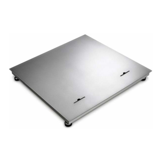
6.5 Cleaning For cleaning or maintenance of the floor balance the weighing plate can be opened by two retractable hand grips easily and without health risk for the back. (s. fig.) 6.6 Connecting a display unit Attention Put the connecting cable to the display unit in a manner that it is protected against damage. -
Page 10: Operation
7 Operation Information about • Network connection (power is supplied via the connecting cable of the display unit) • Initial Commissioning • Connection of peripheral devices • Adjustment, linearization and verification (only the complete balance is verifiable, i.e. weighing bridge in conjunction with a suitable display unit) and the correct operation you will in the operating instructions included in the scope of delivery of the display unit. -
Page 11: Operation Limits
7.1 Operation limits • The weighing bridges are designed extremely robust. However the load limits according to the following table should not be exceeded! • Depending on the type of load receptacle, the static carrying capacity, i.e. the maximum admissible load is: Model 600V40SM 600V40M... -
Page 12: Operation With Access Ramps
Model 1500V40M 3000V40M 3000V40LM Weighing ranges 1500 kg 3000 kg 3000 kg 1500 kg 3000 kg 3000 kg With centrical load With side stress 1000 kg 2000 kg 2000 kg With one-sided loading 500 kg 1000 kg 1000 kg With single-wheel load 250 kg 250 kg 250 kg... -
Page 13: Servicing, Maintenance, Disposal
Do not use water jet or high-pressure cleaner. 8.3 Servicing, maintenance The appliance may only be opened by trained service technicians who are authorized by KERN. Ensure that the weighing system is regularly calibrated, see chap. 3.5 Testing instruments control. -
Page 14: Instant Help
8.5 Instant help In case of an error in the program process, briefly turn off the balance and disconnect from power supply. The weighing process must then be restarted from the beginning. Help: Fault Possible cause • Draught/air movement The displayed weight is permanently changing •... -
Page 15: Service Documentation
9 Service documentation • This chapter is only intended for a balance specialist! • At every each corner of the weighing bridge a DMS weighing cell is installed. • The analogue-digital transformation occurs in the display unit. Also all the balance and country-specific data are stored there. 9.1 Verification data and tolerances Verification data and tolerances as per OIML 0,75... -
Page 16: Check And Adjustment Of The Corner Load
9.2 Check and adjustment of the corner load Check of the corner load: • Place the test weights in the centre of the load plate and tare. • The balance displays -0-. • Place the test weights successively on all four corners. -
Page 17: Overload Settings
10 Overload settings Platform type Platform dimension Loadcell Class Cable- (mm) Type length (kg) KKP 600V40SM 1000x1000x110 KPZ502E-3N DE-16-EC-PTB001 1000 10000 3000 KKP 600V40M 1250x1500x110 KPZ502E-3N DE-16-EC-PTB001 1000 10000 3000 KKP 1500V40SM 1000x1000x110 KPZ502E-3N DE-16-EC-PTB001 1000 10000 3000 KKP 1500V40M 1250x1500x110 KPZ502E-3N DE-16-EC-PTB001...
Need help?
Do you have a question about the KKP V40 and is the answer not in the manual?
Questions and answers