Table of Contents
Advertisement
Available languages
Available languages
Quick Links
Installationsanleitung Wiegebalken
Installation instructions weighing beams
Mode d'emploi barres peseuses
KERN KFA_V20
Version 1.4
02/2017
KERN & Sohn GmbH
Ziegelei 1
D-72336 Balingen
E-Mail: info@kern-sohn.com
Tel: +49-[0]7433- 9933-0
Fax: +49-[0]7433-9933-149
Internet: www.kern-sohn.com
KFA V20-IA-def-1714
Advertisement
Chapters
Table of Contents

Related Manuals for KERN KFA 600V20S


Summary of Contents for KERN KFA 600V20S
- Page 1 KERN & Sohn GmbH Ziegelei 1 Tel: +49-[0]7433- 9933-0 D-72336 Balingen Fax: +49-[0]7433-9933-149 E-Mail: info@kern-sohn.com Internet: www.kern-sohn.com Installationsanleitung Wiegebalken Installation instructions weighing beams Mode d’emploi barres peseuses KERN KFA_V20 Version 1.4 02/2017 KFA V20-IA-def-1714...
- Page 2 Weitere Sprachversionen finden Sie online unter www.kern-sohn.com/manuals Další jazykové verze najdete na webu pod adresou www.kern-sohn.com/manuals Más versiones de idiomas se encuentran online bajowww.kern-sohn.com/manuals Vous trouverez d’autres versions de langue online sous www.kern-sohn.com/manuals Further language versions you will find online under www.kern-sohn.com/manuals Trovate altre versioni di lingue online inwww.kern-sohn.com/manuals...
-
Page 3: Table Of Contents
KERN KFA V20 Version 1.4 02/2017 Installationsanleitung Wiegebalken Inhaltsverzeichnis Technische Daten ..................3 Geräteübersicht ..................... 4 Grundlegende Hinweise (Allgemeines) ............5 Dokumentation ........................... 5 Bestimmungsgemäße Verwendung ................... 5 Sachwidrige Verwendung ......................5 Gewährleistung ........................... 5 Prüfmittelüberwachung ....................... 6 Grundlegende Sicherheitshinweise ............. 6 Hinweise in der Betriebsanleitung beachten ................ -
Page 4: Technische Daten
Ables- Vorlast Kabellänge Verbindungskabel Nettogewicht Abmessungen bereich barkeit additiv Anzeige- Wiegebalken ca. Wägeplatte gerät ca. B x T x H KFA 600V20S 800x120x80 KFA 1500V20 1500 1200x120x100 KFA 3000V20 3000 1200x120x100 KFA 3000V20L 3000 2000x120x100 KFA 6000V20 6000 1000 1200x160x80... -
Page 5: Geräteübersicht
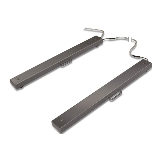
2 Geräteübersicht Abbildungsbeispiel Wägesystem KERN KFA V20 + KFB-TM Anschlusskabel Anzeigegerät Verbindungskabel Wiegebalken Haltegriff zum bequemen Transport Wägezellenfüße und Wägezellen Abdeckung Justierschraube der Wägezellenfüße KFA V20-IA-d-1714... -
Page 6: Grundlegende Hinweise (Allgemeines)
Die Wiegebalken dürfen nicht konstruktiv verändert werden. Dies kann zu falschen Wägergebnissen, sicherheitstechnischen Mängeln sowie der Zerstörung der Wiege- balken führen. Die Wiegebalken dürfen nur gemäß den beschriebenen Vorgaben eingesetzt wer- den. Abweichende Einsatzbereiche/Anwendungsgebiete sind von KERN schriftlich freizugeben. 3.4 Gewährleistung Gewährleistung erlischt bei •... -
Page 7: Prüfmittelüberwachung
Intervall sowie die Art und den Umfang dieser Prüfung zu definieren. Informationen bezüglich der Prüfmittelüberwachung von Wägesystemen sowie der hierfür notwen- digen Prüfgewichte sind auf der KERN- Hompage (www.kern-sohn.com) verfügbar. In seinem akkreditierten DKD- Kalibrierlaboratorium können bei KERN schnell und kostengünstig Prüfgewichte und Wägesysteme kalibriert werden (Rückführung auf das nationale Normal). -
Page 8: Auspacken, Aufstellung Und Inbetriebnahme
6 Auspacken, Aufstellung und Inbetriebnahme 6.1 Aufstellort, Einsatzort Die Wiegebalken sind so konstruiert, dass unter den üblichen Einsatzbedingungen zuverlässige Wägeergebnisse erzielt werden. Exakt und schnell arbeiten Sie, wenn Sie den richtigen Standort wählen. Am Aufstellort folgendes beachten: • Wiegebalken auf eine stabile, gerade Fläche stellen. Das Fundament am Aufstellort muss das Gewicht der Wiegebalken sowie das Gewicht der maximalen Belastung tragen können. -
Page 9: Auspacken Und Aufstellen
6.2 Auspacken und Aufstellen Auspacken: Wiegebalken und Zubehör aus der Verpackung nehmen, Verpackungsmaterial ent- fernen und am vorgesehenen Arbeitsplatz aufstellen. Überprüfen, ob alle Teile des Lieferumfangs vorhanden und unbeschädigt sind. Lieferumfang: • 2 Wiegebalken mit montiertem „Anschlusskabel Anzeigegerät“ und „Verbin- dungskabel Wiegebalken“. -
Page 10: Anschließen Eines Anzeigegerätes
6.3 Anschließen eines Anzeigegerätes Achtung Anschlusskabel so zum Anzeigegerät verlegen, dass es vor möglichen Beschädi- gungen geschützt ist. Beschreibung des Anschlusskabels: Klemme Farbe Zustand EXC+ [IN+] Spannung + SIG + [OUT+] grün Signal + SIG -[OUT-] weiß Signal - EXC -[IN- ] schwarz Spannung - 7 Betrieb... -
Page 11: Wiegebalken Beladen/Entladen
7.1 Wiegebalken beladen/entladen • Die Wiegebalken sind ausgelegt für eine gleichmäßig verteile Last • Fallende Lasten, Schockbelastungen und seitliche Stöße vermeiden. • Die Wiegebalken keinesfalls bewegen, wenn sie beladen sind. Die Last z.B. mit einem Palettenhubwagen, Kran oder Gabelstapler auf beide Wiegebalken platzieren. -
Page 12: Wartung, Instandhaltung, Entsorgung
Lappen reinigen. Darauf achten, dass keine Flüssigkeit in das Gerät eindringt und mit einem trockenen, weichen Tuch nachreiben. 8.3 Wartung, Instandhaltung Das Gerät darf nur von geschulten und von KERN autorisierten Servicetechni- kern geöffnet werden. Sicherstellen, dass das Wägesystem regelmäßig kalibriert wird, s. Kap. 3.5 Prüfmittelüberwachung. -
Page 13: Kleine Pannenhilfe
8.5 Kleine Pannenhilfe Bei einer Störung im Programmablauf sollte das Wägesystem kurz ausgeschaltet und vom Netz getrennt werden. Der Wägevorgang muss dann wieder von vorne be- gonnen werden. Hilfe: Störung Mögliche Ursache • Luftzug/Luftbewegungen Die Gewichtsanzeige ändert sich fortwährend • Vibrationen des Bodens •... -
Page 14: Serviceunterlagen
9 Serviceunterlagen • Dieses Kapitel ist nur für einen Waagen-Fachmann vorgesehen! • An den Wiegebalken befindet sich an jeder Ecke eine DMS-Wägezelle. • Die Analog-Digital-Wandlung findet im Anzeigegerät statt. Dort werden auch alle waagen- und länderspezifischen Daten gespeichert. 9.1 Übersicht, Einstellvorschrift, Toleranzen Prüf- und Einstellvorschrift: Kapazität 600 kg... -
Page 15: Prüfen Und Justieren Der Eckenlast
9.2 Prüfen und Justieren der Eckenlast Prüfen der Eckenlast: • Geeignetes Hilfsmittel z.B. Palette auf beide Wiege- balken legen. Darauf achten dass das Hilfsmittel die Last der Prüfgewichte tragen kann. • Prüfgewichte in der Mitte der Lastplatte auflegen und tarieren. •... -
Page 16: Maßzeichnungen
10 Maßzeichnungen KFA V20-IA-d-1714... - Page 17 KFA V20-IA-d-1714...
- Page 18 KFA V20-IA-d-1714...
- Page 19 KFA V20-IA-d-1714...
-
Page 20: Deadload Settings
11 Deadload settings Kern model Deadload** (kg) Center Overload Corner Overload Loadcell Protection circa (kg) Protection circa (kg) Capacity (kg) **= bereits aufgebrachte Vorlast KFA 600V20S 600kg KFA 1500V20 1000kg KFA 3000V20 1500kg KFA 3000V20L 1500kg KFA 6000V20 3000kg KFA 6000V20L... - Page 22 KERN KFA V20 Version 1.4 02/2017 Installation Instructions Weighing beams Contents Technical data ....................3 Appliance overview ..................4 Basic Information (General) ................5 Documentation ........................... 5 Proper use ..........................5 Improper Use ..........................5 Warranty ............................. 5 Monitoring of Test Resources ....................6 Basic Safety Precautions ................
-
Page 23: Technical Data
Connecting Net weight Dimensions range ability additive display screen cable weighing approx. weighing plate approx. beams approx. W x D x H KFA 600V20S 800x120x80 KFA 1500V20 1500 1200x120x100 KFA 3000V20 3000 1200x120x100 KFA 3000V20L 3000 2000x120x100 KFA 6000V20 6000... -
Page 24: Appliance Overview
2 Appliance overview Illustrative example weighing system KERN KFA V20 + KFB-TM Mains lead display screen Connecting cable weighing beams Handle for easy transport Weighing cell feet and weighing cells Cover adjusting screw for weighing cell feet... -
Page 25: Basic Information (General)
The weighing beams may only be used according to the described conditions. Other areas of use must be released by KERN in writing. 3.4 Warranty Warranty claims shall be voided in case •... -
Page 26: Monitoring Of Test Resources
In KERN's accredited DKD calibration laboratory test weights and weighing systems may be calibrated (return to the national standard) fast and at moderate cost. -
Page 27: Unpacking, Setup And Commissioning
6 Unpacking, Setup and Commissioning 6.1 Installation Site, Location of Use The weighing beams are designed in a way that reliable weighing results are achieved in common conditions of use. To enable exact and fast work, select the right site. On the installation site observe the following: •... -
Page 28: Unpacking And Placing
6.2 Unpacking and placing Unpacking: Remove weighing beams and accessories carefully from packaging, remove packaging material and place device at the planned work place. Verify that there has been no damage and that all packing items are present. Scope of delivery: •... -
Page 29: Connecting A Display Screen
6.3 Connecting a display screen Attention Put the connecting cable to the display unit in a manner that it is protected against damage. Description of the connection cable: terminal Color State EXC+ [IN+] voltage + SIG + [OUT+] green signal + SIG -[OUT-] white signal -... -
Page 30: Load/Unload Weighing Beams
7.1 Load/unload weighing beams • The weighing beams are designed for an evenly spread load • Avoid falling load, shock loads and impacts from the side. • Weighing beams must not be moved when loaded. Place the load onto both weighing beams by using a pallet truck, crane or fork lift. Ensure that the load is not swinging when it is placed onto the weighing beams. -
Page 31: Service, Maintenance, Disposal
8.3 Service, maintenance The appliance may only be opened by trained service technicians who are authorized by KERN. Ensure that the weighing system is regularly calibrated, see chap. 3.5 Testing instruments control. -
Page 32: Instant Help
8.5 Instant help In case of an error in the program process, briefly turn off the weighing system and disconnect from power supply. The weighing process must then be restarted from the beginning. Help: Fault Possible cause • Draught/air movement The displayed weight is permanently changing •... -
Page 33: Service Documentation
9 Service documentation • This chapter is only intended for a balance specialist! • The weighing beams are fitted with a DMS weigh cell at each corner. • The analogue-digital transformation occurs in the display unit. Also all the balance and country-specific data are stored there. 9.1 Overview, setting regulation, tolerances Testing and setting regulations: Capacity... -
Page 34: Check And Adjustment Of The Corner Load
9.2 Check and adjustment of the corner load Check of the corner load: • Place a suitable aid such as a pallet on both weighing beams. Make sure that the aid is designed to bear the weight of the test weight. •... -
Page 35: Dimensioned Drawings
10 Dimensioned drawings KFA V20-IA-e-1714... - Page 36 KFA V20-IA-e-1714...
- Page 37 KFA V20-IA-e-1714...
- Page 38 KFA V20-IA-e-1714...
-
Page 39: Deadload Settings
11 Deadload settings Kern model Deadload** (kg) Center Overload Corner Overload Loadcell Protection circa (kg) Protection circa (kg) Capacity (kg) **= already applied preload KFA 600V20S 600kg KFA 1500V20 1000kg KFA 3000V20 1500kg KFA 3000V20L 1500kg KFA 6000V20 3000kg KFA 6000V20L... - Page 40 KERN KFA V20 Version 1.4 02/2017 Notice d‘installation de la Barres peseuses Table des matières Caractéristiques techniques ................. 3 Aperçu de l’appareil ..................4 Indications fondamentales (généralités) ............. 5 Documentation ........................... 5 Utilisation conforme aux prescriptions ..................5 Utilisation inadéquate ......................... 5 Garantie ............................
-
Page 41: Caractéristiques Techniques
Surface de rainte câble jusqu’à vers les barres env. pesee pesée addition l‘appareil peseuses env. L x P x H nelle d‘affichage env. KFA 600V20S 800x120x80 KFA 1500V20 1500 1200x120x100 KFA 3000V20 3000 1200x120x100 KFA 3000V20L 3000 2000x120x100 KFA 6000V20 6000... -
Page 42: Aperçu De L'appareil
2 Aperçu de l’appareil Exemple de reproduction du système de pesée KERN KFA V20 + KFB-TM Câble de branchement de l’appareil d’affichage Câble de liaison vers la barres peseuses Poignée pour un transport aisé Pieds des capteurs de pesée et capteurs de pesée ... -
Page 43: Indications Fondamentales (Généralités)
3.1 Documentation La notice d'installation comporte toutes les indications pour l’installation et la mise en service des barres peseuses KERN KFP V20. En combinaison avec un appareil d‘affichage, désigné de système de pesée dans ce qui suit, la commande et la configuration sont à relever de la notice de l’appareil d‘affichage. -
Page 44: Vérification Des Moyens De Contrôle
à cette opération sont disponibles sur le site KERN (www.kern-sohn.com). Grâce à son laboratoire de calibrage accrédité DKD, KERN propose un calibrage rapide et économique pour les poids d´ajustage et les systèmes de pesée (sur la base du standard national). -
Page 45: Déballage, Installation Et Mise En Service
6 Déballage, installation et mise en service 6.1 Lieu d´installation, lieu d´utilisation Les barres peseuses ont été construites de manière à pouvoir obtenir des résultats de pesée fiables dans les conditions d´utilisation d´usage. Vous pouvez travailler rapidement et avec précision à condition de les installer à un endroit approprié. -
Page 46: Déballage Et Installation
6.2 Déballage et installation Déballage: Sortir barres peseuses et les accessoires de l’emballage, retirer le matériau d’emballage et installer au poste de travail prévu à cet effet. Contrôler si tous les éléments des fournitures sont livrés et sans dommages. Contenu de la livraison: •... -
Page 47: Branchement D'un Appareil D'affichage
6.3 Branchement d’un appareil d‘affichage Attention Poser le câble de branchement jusqu’à l’appareil d’affichage de manière à ce qu’il soit protégé de possibles endommagements. Description du câble de branchement: Borne Couleur État EXC+ [IN+] rouge Tension + SIG + [OUT+] vert Signal + SIG -[OUT-]... -
Page 48: Chargement / Déchargement Des Barres Peseuses
7.1 Chargement / déchargement des barres peseuses • Les barres peseuses sont conçues pour une charge uniformément répartie • Eviter des charges tombées, des charges par choc ainsi que des chocs latéraux. • Ne pas mouvoir les barres peseuses lorsqu’elles sont sous charge. ... -
Page 49: Maintenance, Entretien, Élimination
8.3 Maintenance, entretien L´appareil ne doit être ouvert que par des dépanneurs formés à cette fin et ayant reçu l´autorisation de KERN. S’assurer que le système de pesée subit un calibrage régulier, voir au chap. 3.5 Vérification des moyens de contrôle. -
Page 50: Aide Succincte En Cas De Panne
8.5 Aide succincte en cas de panne En cas d´anomalie dans le déroulement du programme, le système de pesée doit être arrêté pendant un court laps de temps et coupée du secteur. Le processus de pesée doit alors être recommencé depuis le début. Aide: Panne Cause possible... -
Page 51: Dossier Du Sav
9 Dossier du SAV • Ce chapitre s’adresse exclusivement à un professionnel en matière de balances! • Sur les barres peseuses se trouvent à chaque coin une cellule de pesée à jauge de déformation. • La conversion analogique – digitale s’effectue dans l’appareil d‘affichage. -
Page 52: Contrôle Et Ajustage De La Charge Sur Coin
9.2 Contrôle et ajustage de la charge sur coin Contrôle de la charge sur coin: • Poser un moyen auxiliaire approprié p. ex. une palette sur les deux barres peseuses. Veiller à ce que le moyen auxiliaire puisse supporter la charge des poids de contrôle. -
Page 53: Dimensions
10 Dimensions KFA V20-IA-f-1714... - Page 54 KFA V20-IA-f-1714...
- Page 55 KFA V20-IA-f-1714...
- Page 56 KFA V20-IA-f-1714...
-
Page 57: Poids Mort
Modèle Kern Poids mort **(kg) Surcharge centre Surcharge coin Cellule de pesée Protection env. (kg) Protection env. (kg) capacité (kg) **= précontrainte déjà déployée KFA 600V20S 600kg KFA 1500V20 1000kg KFA 3000V20 1500kg KFA 3000V20L 1500kg KFA 6000V20 3000kg KFA 6000V20L...
Need help?
Do you have a question about the KFA 600V20S and is the answer not in the manual?
Questions and answers