Table of Contents
Advertisement
Quick Links
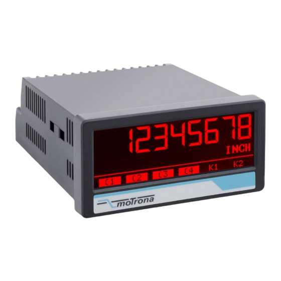
Operating Manual
Display with Start-Stop-Interface for transsonar measurement with absolute and
magnetostrictive position encoders, with touchscreen and graphic display
Product features:
For absolute and magnetostrictive position encoder with Start-Stop-Interface
Bright and high-contrast display with event-dependent color variations
Emulation of a 7-segment display inclusively icons and units
Intuitive and easy parameterization by plain text and touchscreen
5 V / 24 V auxiliary output for encoder supply
Linearization with 24 control points
Numerous features, e. g. scaling, filter, zero offset and counting direction etc.
3.78 x 1.89 inch norm panel housing and IP65 protection
Available options:
DP350:
Option AC:
Option AO:
Option AR:
Option CO:
Option CR:
Option RL:
All options can be combined
motrona GmbH, Zeppelinstraße 16, DE - 78244 Gottmadingen, Tel. +49 (0) 7731 9332-0, Fax +49 (0) 7731 9332-30, info@motrona.de, www.motrona.de
touchMATRIX Indicator DP350
Basic unit with Start-Stop-Interface, 3 control inputs, 5V/24 VDC encoder supply
Power supply 115 / 230 VAC
16 bit analog output, 4 control outputs, serial RS232 interface
16 bit analog output, 4 control outputs, serial RS485 interface
4 control outputs, serial RS232 interface
4 control outputs, serial RS485 interface
2 relay outputs
Advertisement
Table of Contents

Subscribe to Our Youtube Channel
Related Manuals for Motrona touchMATRIX DP350


Summary of Contents for Motrona touchMATRIX DP350
- Page 1 Option CR: 4 control outputs, serial RS485 interface Option RL: 2 relay outputs All options can be combined motrona GmbH, Zeppelinstraße 16, DE - 78244 Gottmadingen, Tel. +49 (0) 7731 9332-0, Fax +49 (0) 7731 9332-30, info@motrona.de, www.motrona.de...
- Page 2 Extension of large display, home screen and display format Legal notices: All contents included in this manual are protected by the terms of use and copyrights of motrona GmbH. Any reproduction, modification, usage or publication in other electronic and printed media as well as in the internet requires prior written authorization by motrona GmbH.
-
Page 3: Table Of Contents
Table of content Safety Instructions and Responsibility ................4 General Safety Instructions ......................4 Use according to the intended purpose ..................4 Installation ............................5 Cleaning, Maintenance and Service Notes..................5 Introduction ........................6 Operation mode ..........................6 Function diagram ..........................7 Electrical Connections .................... -
Page 4: Safety Instructions And Responsibility
Safety Instructions and Responsibility General Safety Instructions This operation manual is a significant component of the unit and includes important rules and hints about the installation, function and usage. Non-observance can result in damage and/or impairment of the functions to the unit or the machine or even in injury to persons using the equipment! Please read the following instructions carefully before operating the device and observe all safety and warning instructions! Keep the manual for later use. -
Page 5: Installation
Please find all respective hints and rules on https://www.motrona.com/en/support --> “[General EMC Rules for Wiring, Screening and Earthing]”. Cleaning, Maintenance and Service Notes To clean the front of the unit please use only a slightly damp (not wet!), soft cloth. -
Page 6: Introduction
Introduction The display device is designed for panel mounting. It is universally applicable, with its intuitive operation, the extensive features and options. Operation mode All functions are can be configured in the parameter menu. The device can be set to one of the following operation modes: DISTANCE (Distance measurement) •... -
Page 7: Function Diagram
Function diagram Electrical Connections The terminal screws should be tightened with a slotted screwdriver (blade width 2mm). 9 111 6 * AC Po w e r * R e la y Ou tp u t 3 4 5 9 10 11 12 13 14 15 16 17 18 19 20 21 22 23 * Se ria l In te rfa ce / C o n tro l Ou t * An a lo g Ou t / Se ria l In te rfa ce / C o n tro l Ou t * N o te : Exte n sio n Mo d u le s... -
Page 8: Auxiliary Voltage Output
Auxiliary Voltage Output Terminal 3 and 4 provide an auxiliary output for supply of sensors and encoders. The output voltage depends on the power supply. DC version AC version The encoder voltage is 24 VDC (± 15%) and The encoder voltage is approx. 1 V lower than should be loaded with max. - Page 9 Continuation “RS-485 inputs and outputs”: DPI-Measurement mode: On the Init line, the Init impulse is sent to position encoder at regular intervals, whose rising edge triggers a measurement. 1…5 µs Init 3…5 µs Start 3…5 µs Stop Dp350_02a_oi_e.docx / Nov-19 Page 9 / 48...
-
Page 10: Control Inputs
Control Inputs The three control inputs at terminal 10, 11 and 12 have HTL PNP characteristics. In the COMMAND MENU the programmable functions for the control inputs can be assigned. Available functions are: display switching, locking the touch screen or release the lock function of the control or relay outputs. -
Page 11: Serial Interface (Option Ao/Ar/Co/Cr)
Serial interface (Option AO/AR/CO/CR) A serial interface (RS232 or RS485) is available at terminal 16, 17 and 18. This interface can be configured in the SERIAL MENU. The serial interface RS232 or RS485 can be used: for easy setup and commissioning of the units ... -
Page 12: Ac Power Supply (Option Ac)
Continuation “Control-Output (Option AO/AR/CO/CR)”: Wiring of the control-outputs: AC Power supply (Option AC) The unit accepts AC supply from 115 to 230 V at the terminals 24 and 25. The power consumption depends on the level of the supply voltage with approx. 3VA and the additional current required at the auxiliary voltage output. -
Page 13: Display And Touch Screen
Display and touch screen Screen structure for parametrization The parameter menus and the parameters are described in chapter 5. Start setup procedure: To edit the parameters, press the touchscreen for 3 seconds. Menu selection: Select the parameter menu via arrow buttons and confirm with “OK”. -
Page 14: Screen Structure In Operation
Screen structure in operation The following displays are available during operation. Depending on the device version and the selected operating mode, only certain representations are displayed. Display with unit and status bar To switch to the next display, press the touch screen. Control - or Relay status are only shown with Option AO, CO, RL. -
Page 15: Error Message
Error Message ERROR: MAXIMUM DISPLAY VALUE Display value is greater than + 99 999 999 ERROR: MINIMUM DISPLAY VALUE Display value is less than - 99 999 999 ERROR: MAX. LARGE DISPLAY VALUE Display value of the large display is greater than + 9999 ERROR: MIN. - Page 16 Continuation “Error Message”: The described error messages are automatically reset as soon as the corresponding display value is within the representable range or the error has been corrected. For the errors "POS. ENC. OUT OF RANGE "and" ENCODER ERROR ", the measurement result is set to"...
-
Page 17: Parameter / Overview-Menu Structure
Parameter / Overview-Menu Structure This section provides an overview of the menus and their parameters. The menu names are printed bold and the associated parameters are listed under the menu name. Depending on the device version and the selected operation mode, only the necessary menus / parameters are shown. Menu / Parameter Menu / Parameter GENERAL MENU... - Page 18 Menu / Parameter Menu / Parameter PRESELECTION VALUES SERIAL MENU PRESELECTION 1 UNIT NUMBER PRESELECTION 2 SERIAL BAUD RATE PRESELECTION 3 SERIAL FORMAT PRESELECTION 4 SERIAL INIT SERIAL PROTOCOL PRESELECTION 1 MENU SERIAL TIMER MODE 1 SERIAL VALUE HYSTERESIS 1 MODBUS PULSE TIME 1 ANALOG MENU...
-
Page 19: General Menu
General Menu OPERATIONAL MODE This parameter determines which measurement function (mode) the device should run. Distance measurement DISTANCE Angle measurement (display in degrees) ANGLE LENGHT PER REVOLUTION ( in millimeters) This parameter represents the reference value for the angle measurement. Here, the distance covered (perimeter) per 360 degrees (in "mm") must be set. - Page 20 Continuation “General Menu“: DECIMAL POINT This value defines the position of the decimal point. This is only a decimal point that can be graphically switched. This does not affect the two scaling factors FACTOR and DIVIDER. No decimal point Decimal point at the specified position 0000000.0 Decimal point at the specified position 000000.00...
- Page 21 Continuation “General Menu“: SCALE UNITS This parameter defines the required engineering unit. This parameter does not affect the calculation of the display value. The number of decimal places must be defined with the parameter DECIMAL POINT, the corresponding scaling must be defined with the parameters FACTOR and DIVIDER. inch feet Default...
- Page 22 Continuation “General Menu“: AVERAGE FILTER (filter for average value) The average value can be switched to avoid display fluctuations. No average value Flowing mean value with 2 cycles Flowing average value with 4 cycles Flowing average value with 8 cycles Flowing mean value with 16 cycles LINEARIZATION MODE This parameter defines the linearization function.
-
Page 23: Encoder Properties
Encoder Properties SAMPLING TIME (S) Period duration between two init pulses (in milliseconds). Corresponds to the time after a new measurement is started and directly affects the reaction time of the device. 00.200 Minimum measurement time 04.000 Default value 16.000 Maximum measurement time VELOCITY (M/S) Waveguide velocity of the encoder (in m/s). -
Page 24: Preselection Values
Preselection Values This menu is used to set the preselection values or the switching points. The preselection values / switching points are always referred to the display value. (Position value relative to the reference zero point or machine zero that was stored in the parameter offset.) This menu is only available for devices with option CO, CR, AO, AR or RL. -
Page 25: Preselection 1 Menu
Preselection 1 Menu This function is only available for devices with option CO, AO or RL. MODE 1 Switching conditions for preselection 1. Output/ relay/ display switches under the following conditions: Absolute value of the display value is greater or equal absolute value of PRESELECTION 1 With HYSTERESIS 1 not equal 0 the following switching condition is 0 |RESULT|>=|PRES|... - Page 26 Continuation “Preselection 1 Menu“: HYSTERESIS 1 This parameter defines the switching hysteresis of the switch-off point for preselection 1 No switching hysteresis … 99999 Switching hysteresis of 99999 PULSE TIME 1 (S) Duration of output pulse for the switching condition of preselection 1 0,000 No output pulse (static signal) …...
- Page 27 Continuation “Preselection 1 Menu“: START UP DELAY 1 (S) Start-up suppression for the switching condition of preselection 1. Time to start the monitoring function. This adjustment is only valid for the switching condition |RESULT|<=|PRES| or RESULT<=PRES and mode SPPED and PROCESS TIME. (Start Up Delay 3 and 4 have an automatic start up suppression).
-
Page 28: Preselection 2 Menu
Preselection 2 Menu MODE 2 Switching conditions for preselection 2., see chapter PRESELECTION 1 MENU (except the trailing value) see chapter PRESELECTION 1 MENU Trailing preselection 2: 6 RES>=PRES-TRAIL Display value is greater or equal to PRESELECTION 1 – PRESELECTION 2 ON, PRESELECTION 2 is the trailing preselection from PRESELECTION 1. -
Page 29: Preselection 3 Menu
Preselection 3 Menu MODE 3 Switching conditions for preselection 3., see chapter PRESELECTION 1 MENU (except the trailing value) See chapter PRESELECTION 1 MENU Trailing preselection 3: RES>=PRES- Display value is greater or equal to PRESELECTION 4 – PRESELECTION 3 ON, TRAIL PRESELECTION 3 is the trailing preselection from PRESELECTION 4. -
Page 30: Preselection 4 Menu
Preselection 4 Menu MODE 4 Switching conditions for preselection 4., see chapter PRESELECTION 1 MENU (except the trailing value) See chapter PRESELECTION 1 MENU Trailing preselection 4: 6 RES>=PRES-TRAIL Display value is greater or equal to PRESELECTION 3 – PRESELECTION 4 ON, PRESELECTION 4 is the trailing preselection from PRESELECTION 3. -
Page 31: Serial Menu
Serial Menu This menu defines the basic settings of serial interface. This function is only available for devices with option CO or AO. UNIT NUMBER This parameter defines serial device addresses. The addresses between 11 and 99 can be assigned to the devices. - Page 32 This parameter enables the Modbus protocol and determines the Modbus address. For details of the Modbus communication please refer to the additional manual Modbus_RTU Serial interface is using Lecom protocol (Motrona default protocol) Serial interface is using Modbus RTU protocol. The set value is the Modbus address of 1 …...
-
Page 33: Analog Menu
Analog Menu This menu defines the basic settings of the analog output. The analog output always refers to the absolute measurement result. This function is only available for devices with option AO or AR. ANALOG FORMAT This parameter defines the output characteristics. In the output format (-10... + 10 V), the polarity of the analog output depends on the polarity of the display value. -
Page 34: Command Menu
Command Menu INPUT 1 ACTION (function Input 1) This parameter defines the function of the input “Ctrl. In 1”. No function Power fail-safe stored transfer of the current position to the parameter (d) (s) "offset". (Includes command "STOP SET TO ZERO" to cancel any RESET/SET VALUE previous relative measurements) Example Application: non-volatile setting of the machine zero point. - Page 35 Continuation “Command Menu“: (s) = static switching (level evaluation) INPUT CONFIG must be set to active LOW / HIGH (d) = dynamic switching (edge evaluation) INPUT CONFIG must be set to RISING/FALLING EDGE INPUT 1 CONFIG This parameter defines the switching characteristics of the input “Ctrl. In 1”. ACTIVE LOW Active at „LOW“...
-
Page 36: Display Menu
Display Menu COLOR This parameter defines the display color. Event-depending change of the display color by a switching condition is possible (see PRESELECTION 1…4 MENU) Event-depending changes are only available for devices with option CO, AO or RL. 0 RED Red display 1 GREEN Green display... - Page 37 Continuation “Display Menu“: START DISPLAY This parameter defines the start display after switching on the device. STANDARD Single-line display with status bar LARGE Large display. (only with activated parameter "LARGE DISPLAY"!) Display of keyboard commands (only with "SKIP COMMANDS".setting COMMAND ...
-
Page 38: Linearization Menu
Linearization Menu The linearization function is defined in this menu. This menu will only be showed, if the LINEARIZATION MODE in GENERAL MENU is selected. Linearization description and examples are shown in the appendix. P1(X) … P24(X) X-coordinate of the linearization point. This value representing the display value which the unit show in the display without linearization. -
Page 39: Appendix
Drivecom Protocol according to ISO 1745. More details can be found in our separate description SERPRO (Drivecom) or Modbus_RTU (Modbus), see www.motrona.de. To request for a data transmission you must send the following request string to the converter:... -
Page 40: Parameter / Serial Codes
Parameter / serial codes Menu Name Serial Code Default GENERAL MENU OPERATIONAL MODE GENERAL MENU 99999999 LENGHT PER REV. (MM) 1000000 GENERAL MENU DISPLAY FORMAT GENERAL MENU FACTOR -99999999 99999999 GENERAL MENU DIVIDER -99999999 99999999 GENERAL MENU ADDITIVE VALUE -99999999 99999999 GENERAL MENU DECIMAL POINT... - Page 41 Continuation “Parameter / serial codes”: Menu Name Serial Code Default PRESELECTION 2 MENU MODE 2 PRESELECTION 2 MENU HYSTERESIS 2 99999999 PRESELECTION 2 MENU PULSE TIME 2 (S) 60000 PRESELECTION 2 MENU OUTPUT TARGET 2 PRESELECTION 2 MENU OUTPUT POLARITY 2 PRESELECTION 2 MENU OUTPUT LOCK 2 PRESELECTION 2 MENU...
- Page 42 Continuation “Parameter / serial codes”: Menu Name Serial Code Default COMMAND MENU INPUT 1 ACTION COMMAND MENU INPUT 1 CONFIG. COMMAND MENU INPUT 2 ACTION COMMAND MENU INPUT 2 CONFIG. COMMAND MENU INPUT 3 ACTION COMMAND MENU INPUT 3 CONFIG. COMMAND MENU COMMAND MENU COMMAND MENU...
- Page 43 Continuation “Parameter / serial codes”: Menu Name Serial Code Default LINEARIZATION MENU P15(X) -99999999 99999999 LINEARIZATION MENU P15(Y) -99999999 99999999 LINEARIZATION MENU P16(X) -99999999 99999999 LINEARIZATION MENU P16(Y) -99999999 99999999 LINEARIZATION MENU P17(X) -99999999 99999999 LINEARIZATION MENU P17(Y) -99999999 99999999 LINEARIZATION MENU P18(X) -99999999...
-
Page 44: Linearization
Linearization The linearization function of this unit allows converting a linear input signal into a non-linear developing (or vice versa). There are 24 programmable x/y coordinates available, which can be set in any desired distance over the full conversion range. Between two coordinates, the unit uses linear interpolation. - Page 45 Application Example: The picture below shows a watergate where the opening is picked up by means of an incremental encoder. We would like to display the clearance of the gate "d", but the existing encoder information is proportional to the angular information φ. Dp350_02a_oi_e.docx / Nov-19 Page 45 / 48...
- Page 46 Dp350_02a_oi_e.docx / Nov-19 Page 46 / 48...
-
Page 47: Technical Specifications
Technical Specifications: Technical Specifications: Connections: Connector type: screw terminal, 1.5 mm² / AWG 16 Power supply (DC): Input voltage: 18 … 30 VDC Protection circuit: reverse polarity protection Consumption: approx. 100 mA (unloaded) Fuse protection: extern: T 0.5 A Power supply (AC): Input voltage: 115…230 VAC, 50…60 Hz (Option AC) - Page 48 Continuation “Technical Specifications”: Serial interface: Format (Option A0/CO): RS232 (Option AO/AR/CO/CR) Format (Option AR/CR) RS485 Baud rate: 9600, 19200 or 38400 baud Display: Type: LCD (backlight) Display range: 8 digits plus sign (-99999999 … 999999999) Digit height 13 mm height Color: red / green / yellow (switchable) Operation:...
Need help?
Do you have a question about the touchMATRIX DP350 and is the answer not in the manual?
Questions and answers