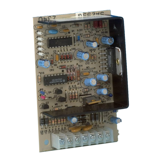
ADEMCO 745x3 - Voice Siren Driver Installation Manual
- Installation instructions (2 pages)
Advertisement

Features
- Generates voice output in English, French, and Spanish.
- Separate messages for FIRE and BURGLARY conditions.
- Separate siren sounds for FIRE and BURGLARY conditions.
- Terminal strip for secure connection to control panet.
- Selectable input level (High/Low) for FIRE/BURGLARY inputs.
- Supervision feature for speaker and speaker wiring.
- Compatible with most control panels.
- Sounder options for bell ringbacWbell test
- Compatible with B—16-ohm speakers.
- Operates on 12-16V DC.
- Small compact size for easy insta}laqion using double-sided tape (packed separately) — measures only 4" x 2-5/8" x 1-1/4".
Output Selection
The voice driver can be programmed for the desired alarm output on burglary and fire by means of jumpers JPI frrough JP4, as indicated in Table 1. See Figure 1 for location of jumpers.

Table 1. Output Selection
Bell TesURlngback Options (JP5)
If jumper JP5 is kept intact, the siren driver will generate a steady sound for belE test and bell ringback conditions.
If the jumper is cut. a warbled sound will be generated fot bell test/ringback conditions. Note: If this mode is selected, a lire signal will momentarily generate a warbled siren sound for the initial portion of the siren sound and then revert to the normal siren sound and voice message.
Burglary Signal Polarity (JPG)
intact = High(12V+), cut = Low (OV).
The burglary message may be activated by either a steady logic high or a steady 'ogic low, as provided by the control panel (refer to the control panel's instructions).
When jumper JP6 is intact, activation is by a logic high (12V+) at terminal 2. Cut jumper JP6 for activation by a logic low Note that a pulsing high or low (pulse width 0.25 to I.75 seconds, that is provided by some panels) connected to the Burglary/Fire input (terminal 2) wilt be interpreted as a Fire condition and will produce the fire message.
Fire Signal Polarity (JP7)
Intact High (1 2V+), cut = Low (OV).
As in the case of Burglary signat polarity, the fire message may be activated by either a logic high or logic low, but at terminal 3 (Ademco control panels provide a logic high). When jumper JP7 is intact, activation is by a logic high (1 2V+). Cut jumper JP7 for activation by a logic low
Burglary Messages

Fire Messages

Wiring Connections
 Wiring connections to the terminals are as follows. Refer to Figure 1 (and Tabte 2 for Ademco products).
- SUPV: SPEAKER-WIRING SUPERVISION (OPTIONAL).
For supervision of the speaker and associated wiring, connect to a 24-hour zone that is activated by a short,
Removing the speaker or shorting either speaker terminal to ground will appear as a short on the zone, Note that in seriesconnected multiple speaker systems, cutting any speaker will trip the control panel's supervision zone. In parallel-connected speaker systems, each branch must be cut before the control panel's supervision zone will trip. - B/F: BURGLARY/FIRE WPUT:
Connect the control panel's Burglary (steady) output to this terminal. Thi: s terminat may also be used to trip the FIRE message if the control provides a pulsing output for fire (re-programming may be required). In this case, no connection to terminal 3 is required. - F: FIRE INPUT:
Connect the control panel's output designated as the FIRE (steady) vo; tage output to his terminal (unless this output was connected to terminal 2). - SPKR& 5 SPKR: SPEAKER TERMINALS:
Connect an 8-ohm or i6-ohm 15-watt speaker to these terminals. See Figure 3 for multiple speaker configurations.
![ADEMCO - 745x3 - Wiring Connections - Example 2 Wiring Connections - Example 2]()
- (+): 12VDC(+) POWER INPUT:
Connect to a 12VDC (+) source on the control; since the driver can draw as much as 1.1 amps, it may be necessary in some cases (see Table 2 for Ademoo products) to connect to the system's back-up battery through a 2 amp in-line fuse, as shown in Figure 2.
![ADEMCO - 745x3 - Wiring Connections For Ademco Control Panels Wiring Connections For Ademco Control Panels]()
![ADEMCO - 745x3 - Wiring Connections - Example 3 Wiring Connections - Example 3]()
- (-): 12VDC(-) POWER INPUT:
Connect to a ground point on the control panel
![ADEMCO - 745x3 - Wiring Connections - Example 4 Wiring Connections - Example 4]()
We recommend that the Voice Siren Driver be mount~ in <hecontrol cabinet, not remotely.

Documents / ResourcesDownload manual
Here you can download full pdf version of manual, it may contain additional safety instructions, warranty information, FCC rules, etc.
Download ADEMCO 745x3 - Voice Siren Driver Installation Manual
Advertisement


Need help?
Do you have a question about the 745x3 and is the answer not in the manual?
Questions and answers