Advertisement
OVERVIEW
- Operating frequency 868.150 MHz
- Redundant transmission by radio command with selectionable transmission time
- Internal sensor and input for remote sensor
- Possibility of locking or limiting the knob
- Low battery indicator
- Heating/Cooling selection can be managed by the thermostat or on the receiver
This device is a radio-controlled electronic thermostat to control the temperature in industrial and commercial spaces as well as domestic environments.
The thermostat can control heating and cooling systems. The LED on the front warns when the batteries are low.
Its main characteristic is the lack of electrical connections; indeed the ON and OFF signals are transmitted to the receiving unit by radio, making this device easy and cheap to install, especially when there is no existing electrical system available.

OPERATION
Heating/cooling mode
By adjusting the JP3 connector, shown by  in Fig. 5, the thermostat can be set in Heating or Cooling mode:
- Heating
Jumper inserted to the left (F of Fig. 5) - Cooling
Jumper inserted to the right (G of Fig. 5)
Periodically the thermostat transmits a radio command to the receiver containing the information about the room temperature, setpoint temperature and the heating/cooling status. The receiver starts to compare the desired temperature with the room temperature and adjusts accordingly by turning the relay output on or off.
The receiver can also ignore the heating/cooling setting coming from the thermostat if the same data comes from an associated timer thermostat or if the selection is decided on the receiver using the dedicated input.
The receiver is able to adjust the temperature in the room where the thermostat is installed with the two setpoint temperatures: comfort and economy.
The comfort temperature corresponds to the temperature set on the knob, whereas temperature set on the knob minus a fixed value (set on the receiver) in the heating mode (in the cooling mode, Tcomfort + fixed reduction).
The reduction function can be overridden by the receiver by connecting a hourly programmer to the dedicated input or controlled by an associated timer thermostat. For further information, see the instructions for the receiver.
Selecting the sampling interval
To make sure that the batteries last for a long time, the thermostat waits for a length of time between one transmission and another that can be chosen as 3 or 10 minutes by adjusting on an internal jumper JP2, shown by  in Fig. 5.
- Sampling every 10 minutes
Jumper inserted to the left (C of Fig. 5) - Sampling every 3 minutes
Jumper inserted to the right (D of Fig. 5) - Sampling every 3 minutes with reduced power
Jumper not inserted (E of Fig. 5)
The 3-minute option should be chosen if used with quick heating/cooling systems, whereas the 10-minute option also allows excellent accuracy and comfort with radiator systems and floor heating systems. If the thermostat is installed in close proximity to the receiver (<15 metres), you can also choose the 3-minute mode with reduced power.
The batteries will last longer when you choose the longer period. Due to the updating period, the output will not automatically be updated when the setpoint knob is moved. You will have to wait for 3 or 10 minutes in the worst case in accordance with the length of time chosen.
Enabling the remote probe
The thermostat leaves the factory set up for operation using the internal probe.
As an alternative to the internal probe, a remove probe can be connected to two terminals shown by  in Fig. 5. When connecting the remote probe, remove the jumper JP1, shown by
  in Fig. 5 to disable the internal probe.
Make sure that you are using the right type of remote probe and observe the maximum length of wires allowed.
Knob
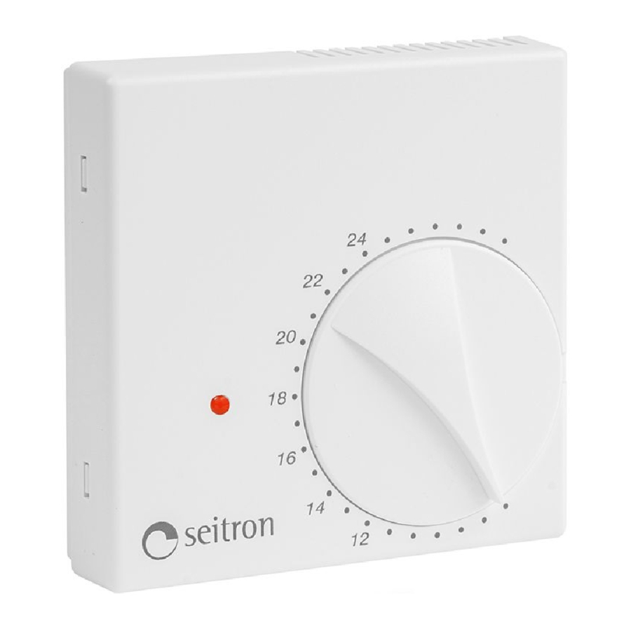
Using the regulation knob  , the setpoint temperature can be set around which the temperature check will be carried out in the range of 6.. 30°C.
Limiting the rotation of the knob
The field within which the knob rotates can be reduced by adjusting in the following way:
- Lifting the knob by using a screwdriver as a lever in the appropriate guide
![]() .
. - Pull out the mechanical clamps set on the side of the knob housing
![]() and position them as shown in the example in Fig. 4 with
and position them as shown in the example in Fig. 4 with ![]() and
and ![]() . The field of rotation is reduced in this way as in the arch shown by
. The field of rotation is reduced in this way as in the arch shown by ![]() .
. - Reinsert the knob by positioning it in the right angle so that it correctly comes into connect with its spindle and then pressing it down to the bottom.
 .
. and position them as shown in the example in Fig. 4 with
  and
and  . The field of rotation is reduced in this way as in the arch shown by
  .
.Red LED: low battery warning
The red warning LED  on the front of the product notifies when the batteries are low and must be replaced. The LED usually remains always off, whereas when it shows that the battery is low it comes on for a moment every 20 seconds approximately.
Furthermore, when the batteries are inserted for the first time, the red LED comes on and stays lit for 2 seconds. This indicates that the batteries have been inserted correctly and that the thermostat is working properly.
The LED also performs a function during the test stage. (See 'System configuration' paragraph.)
SYSTEM CONFIGURATION
Before installing the thermostat in the desired position, it is necessary to check that the receiver correctly receives its signals. The operation is carried out by enabling the 'Test' function, described below.
Open the thermostat, as shown in the 'Installation' paragraph, and insert the batteries while respecting the correct polarity; in  the internal position of the batteries can be seen. When the batteries are inserted for the first time, the red LED comes on and stays lit for 2 seconds. This indicates that the batteries have been inserted correctly and that the thermostat is working properly.
The 'Test' function of the thermostat is enabled by pressing the 'Test' button for a second, shown by  in Fig. 1-5. P4 ress the 'Test' button again to end the function.
The 'Test' button can also be pressed without removing the cap by adjusting with a small screwdriver through the front slots as shown by in Fig. 1.
In the 'Test' mode, the thermostat continuously transmits ON and OFF commands to the receiver with a pause of approximately 2 seconds between one and the next. The LED flashes every 2 seconds. If the 'Test' mode isn't finished using the button, it will end automatically after approximately 12 minutes.
The 'Test' mode must be used to self-learn the address code of the thermostat on the receiver.
When the thermostat is positioned in the desired area, make sure that it still communicates properly with the receiver.
If the thermostat is positioned too far away from the receiver, the relay output will always remain on or off. In this case, it is recommended that a better position is found, possibly closer to the receiver, and make sure that it isn't in the vicinity of metal screens or reinforced concrete walls which could weaken the radio transmission. The signal quality can be monitored in the receiver; see the relative documentation for further information.
INSTALLATION
Before installing the thermostat, make sure that the radio signals transmitted are correctly received by the receiving unit.
We hereby remind you that the thermostat should be installed away from sources of heat, drafts and particularly cold or hot walls for the correct regulation of the room temperature.
Perform the following operations to install the thermostat:
- Remove the knob by using a small screwdriver as a lever in the appropriate guide, shown by
![]() in Fig. 1-2.
in Fig. 1-2. - Remove the cap by using a screwdriver on the plastic teeth, shown by
![]() in Fig. 1-2-3, by applying a little 10 pressure between the tooth and the hole in the plastic, without pressing down directly on it to make sure that it doesn't break.
in Fig. 1-2-3, by applying a little 10 pressure between the tooth and the hole in the plastic, without pressing down directly on it to make sure that it doesn't break. - Correctly insert the batteries respecting the correct polarity. Do not use dead batteries. Use alkaline batteries and perform the Test function. (See 'System configuration' paragraph.)
- Having identified the best position for installation, fix the bottom of the thermostat to the walls using two screws, using the two holes with a distance between the 60mm axes.
 in Fig. 1-2-3, by applying a little 10 pressure between the tooth and the hole in the plastic, without pressing down directly on it to make sure that it doesn't break.
Take care not to damage the internal electronic circuits when working with tools close to the holes of the screws.
- Configure the thermostat; see the 'OPERATION' or 'SYSTEM CONFIGURATION' paragraph.
- Close the thermostat by positioning the cap so that the knob's spindle comes into contact with the relative hole and then press it slightly until the four plastic teeth click.
- Reinsert the knob by positioning it in the right angle so that it correctly comes into connect with its spindle and then pressing it down to the bottom.
TECHNICAL FEATURES
| Power supply: | 2 x 1.5V= alkaline AAA type batteries | |
| Duration of the batteries: | >6 years at TX every 10 min >2.5 years at TX every 3 min >4 years at TX every 3 min with reduced power | |
| Measurement range: | -5.0..+46.1°C | |
| Regulation range: | 6.. 30°C | |
| Precision: | ± 1°C | |
| Resolution: | 0.1°C | |
| Hysteresis: | defined on the receiver | |
| Type of sensor: | NTC 100k @ 25°C internal | |
| Remote sensor: | cod. STL OTS A 150 (optional) | |
| Maximum length of the wires to the remote sensor: | 3 m | |
| Frequency: | 868.150 MHz | |
| Output power (ERP): | < 25 mW | |
| Modulation: | GFSK | |
| Type of antenna: | Internal | |
| Max. distance from receiver: | >300 m in free field >50 m in buildings (depending on the building and environment) | |
| Protection rating: | IP 30 | |
| Operating temp.: | 0.. 40°C | |
| Storage temp.: | -10.. +50°C | |
| Humidity limits: | 20.. 80% RH (non-condensing) | |
| Enclosure: | Material: | ABS V0 self-extinguishing |
| Colour: | Signal White (RAL 9003) | |
| Maximum dimensions: | 85 x 85 x 29 mm (WxHxD) | |
| Weight: | ~ 130 g | |
| EMC normative references: | ETSI EN 301 489-3 v1.4.1 | |
| LVD normative references: | EN 60730-1 (1996) | |
| R&TTE normative references: | ETSI EN 300 220-2 v2.1.1 | |

- To determine the correct position one must ensure that the radio signals transmitted are correctly received by the receiving unit.
- To adjust properly room temperature, install the thermostat far from heat sources, airstreams or particularly cold walls (thermal bridges). When the remote sensor is used in conjunction with the thermostat, then this note is to be applied to the remote sensor itself.
- For remote version all wirings must be made using wires with 1,5 mm² minimum section and no longer than 3 m. Do not use same duct for signal wires and mains.
- Installation and electrical wirings of this appliance must be made by qualified technicians and in compliance with the current standards.
| TROUBLESHOOTING | ||
| SYMPTOM | PROBABLE REASON | REMEDY |
| In the 'heating' mode, even though the setpoint knob is on maximum, the red LED still remains OFF and the relative output in the receiver also remains OFF. | The red LED indicator does not continuously indicate the status of the output relay. Furthermore, the output relay in the receiver does not come on or off instantly. The status is updated every 3 or 10 minutes. (See the 'How it works' section.) | This is a normal operation. |
| When the batteries are inserted for the first time, the red LED does not come on for 2 seconds. | The batteries are dead or have been inserted wrongly. The polarity must be respected. | Correctly insert new batteries. The 'Installation' paragraph explains how to perform the operation correctly. |
| Due to an extremely low consumption of electricity in the circuit, if the batteries had already been inserted recently, it is possible that a small amount of energy is still present even if there is no power supply, therefore the thermostat momentarily behaves as if the batteries had not been removed at all. | Press the internal test button for a second to reset the internal electronic circuits. | |
| When the batteries are inserted, also by pressing the 'Test' button , the LED does not come on for 2 seconds, briefly flashes and the thermostat doesn't work. | The batteries are dead. | Correctly insert new batteries. The 'Installation' paragraph explains how to perform the operation correctly. |
| In the 'Test' mode, the LED in the thermostat flashes correctly, but the relay of the relative output in the receiver still remains off. | The address code of the thermostat hasn't been correctly self-learnt by the receiving unit or the self-learning procedure hasn't been carried out on any of the unit's channels. | Carefully following the 'self-learning' procedure described on the instructions sheet of the receiving unit to join the transmitter to the desired channel. |
Via Prosdocimo, 30
I-36061 BASSANO DEL GRAPPA (VI)
Tel.: +39.0424.567842
Fax.: +39.0424.567849
http://www.seitron.it
e-mail: info@seitron.it

Documents / Resources
References
Download manual
Here you can download full pdf version of manual, it may contain additional safety instructions, warranty information, FCC rules, etc.
Download Seitron NEW WAVE, DTP F85 BC0 0SE - Wireless Room Temperature Thermostat Manual
Advertisement


Need help?
Do you have a question about the NEW WAVE and is the answer not in the manual?
Questions and answers