Table of Contents
Advertisement
Quick Links
Advertisement
Table of Contents

Subscribe to Our Youtube Channel
Related Manuals for Kistler 8743A Series


Summary of Contents for Kistler 8743A Series
- Page 1 Instruction Manual Shock Accelerometers Type 8743A… ä 002-335e-01.19...
- Page 2 Shock Accelerometers Page 1 Instruction Manual Shock Accelerometers Type 8743A… Kistler Instrument , 75 John Glenn Drive , Amherst, NY 14228-2171, Tel: 716-691-5100 002-335e-01.19...
-
Page 3: Table Of Contents
Securing Cables ........................9 Operation ............................10 Powering ........................... 10 7.1.1 Using “Built In” Power Sources ..................10 7.1.2 Kistler Couplers ........................11 7.1.3 The Constant Current Power Supply/Coupler ..............11 7.1.4 Sensor Power-Up ....................... 14 7.1.5 Overload Recovery ......................14 7.1.6... -
Page 4: Introduction
Information in this document is subject to change without notice. Kistler reserves the right to change or improve its products and make changes in the content without obligation to notify any person or organization of such changes or improvements. -
Page 5: Precautions
Power the instrument in accordance with the instructions in section 6 of this manual. Precautions Kistler sensors are thoroughly tested before leaving the factory. To maintain safe and reliable operation, it is important to follow the instructions herein. * Do not mount accelerometers on high voltage surfaces. -
Page 6: Shock Accelerometer Types
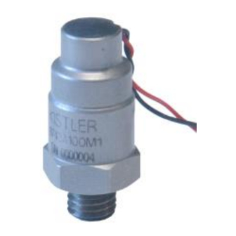
Table 1: Manual Nomenclature 4 General Description Kistler shock accelerometers are shear mode shock and vibration measuring instruments. These units are intended for pyroshock testing, metal-to-metal impact studies, drop testing, etc. A self- generating piezoelectric sensing element is used in conjunction with the built-in, internal circuit Piezotron* impedance converter. -
Page 7: Technical Information, Functional Description
Shock Accelerometers Page 6 5 Technical Information, Functional Description Piezoelectric Measurement Concept Piezoelectric accelerometers convert acceleration into an electric charge. The charge derived by the accelerometer is proportional to the force acting on the internal quartz (piezoelectric) element. Accordingly, the mechanical variable (acceleration) is derived from a force measurement. -
Page 8: Installation
Shock Accelerometers Page 7 Low impedance accelerometers are ideally suited for applications where long or moving cables are required; in high humidity or other contaminated atmospheres. They eliminate the problems associated with high impedance output types by providing a low impedance voltage signal with enhanced high frequency response. -
Page 9: Stud Mounting
Shock Accelerometers Page 8 Stud Mounting The stud on both units is an integral part of the mounting base and thus not removable. The following guidelines should be followed when mounting shock accelerometers. Drill and tap an adequate hole to ensure a flush mount of the accelerometer. -
Page 10: Securing Cables
Shock Accelerometers Page 9 Outline dimensions used in mounting are shown in Figure 3. Type designations that include the letter E are sized in meteric units. Surface Dia. L1 inch [mm] L2 inch [mm} 3/8” minimum 10-32 UNF 0.156 [4.0] 0.315 [8.0] 1/2”... -
Page 11: Operation
Figure 5: Incorrect Cable Strain Relief See Section 8.5 for information on cables available from Kistler. 7 Operation Piezoelectric accelerometers are self generating transducers. While the quartz piezoelectric sensor does not require an external power source, it is necessary to provide power to the shock acceleometer’s... -
Page 12: Kistler Couplers
7.1.2 Kistler Couplers Kistler offers a comprehensive line of power supply/couplers and dual mode amplifiers. If the user is utilizing these instruments, they are designed for compatibility with K-Shear accelerometers. The chart below provides a listing of available power supply/couplers. Please request data sheets on specific models. - Page 13 Shock Accelerometers Page 12 Quartz Element To Coupler Electrometer Amplifier Sensor PIEZOTRON AMPLIFIER Figure 6: Simplified Diagram of the Shock Accelerometer The source resistor (Rs), while located in the coupler, is a part of the source follower circuit. In order for the Piezotron to provide enough gain, Rs must have a high dynamic resistance while being able to provide enough current (low DC resistance) as not to affect the high frequency response of the system.
- Page 14 Shock Accelerometers Page 13 (See Figure 9). The following equations are provided to calculate the maximum full scale voltage available when operating with a reduced voltage. Maximum positive amplitude: Es 1) - Maximum negative amplitude: Eb - Where: Fs = Full scale output (peak) ES = DC supply voltage (sometimes called compliance voltage) Eb = bias voltage (from calibration certificate) Figure 8:...
-
Page 15: Sensor Power-Up
Shock Accelerometers Page 14 7.1.4 Sensor Power-Up Figure 10: Behavior Of The Output Signal During Power-Up When power is first applied to the sensor, (through an AC coupled coupler) a voltage will appear at the output of the coupler (See Figure 10). -
Page 16: Driving Long Cables
For the user's convenience a chart is provided (See Table 5). The values given are based on a cable capacitance of 30 pF/foot (98 pF/m). The list of cables available from Kistler can be found in section 9.3. All cables in this section are 30pF/ft (98 pF/m). except for the 1331, 1635 and 1639 which are 20 pF per foot(65 pF/m). - Page 17 Shock Accelerometers Page 16 The current requirements can be calculated using the following equation: Where: Current Amperes Frequency Capacitanc Farads Output Volts, Peak Never use more current than required to make the desired measurement. Never exceed the maximum current. If a requirement calls for 1,000 feet (300m) of cable and the maximum frequency of interest is only 5 kHz than the user should select (From Table 5) 5 mA of current rather than the 10 mA required...
-
Page 18: Frequency Response Limits
Shock accelerometers are specified with maximum variations of ±5% to ±10%. Kistler uses the industry standard reference frequency of 100Hz. Many users may be more familiar with the common frequency response standard for electronic equipment which is generally *3dB. - Page 19 Shock Accelerometers Page 18 Where: undamped natural (resonant) frequency (Hz) frequency given point curve (Hz) output accelerati mounting base reference accelerati factor amplitude increase resonance Quartz accelerometers have a Q of approximately 10 to 40 and therefore the phase angle can be written as: ...
-
Page 20: Low Frequency Limitations - Transducer
Shock Accelerometers Page 19 Figure 13: Typical Frequency Response of a Piezoelectric Accelerometer Section 5 provides important information regarding mounting. It is important that these instructions are followed to ensure optimal transmissibility at high frequencies. Mounting to rough surfaces, using soft adhesives and magnetic mounts will limit the high frequency range to some value lower than the specified frequency range. - Page 21 Shock Accelerometers Page 20 The high pass filter has a time constant (*) as determined by the capacitance and resistance of the internal amplifier gate circuit. The time constant is defined as the time required for the capacitors to reach 63.3% of full charge as determined by *=RC. As capacitance and/or resistance is increased, the time constant becomes longer thus an increase in the low frequency response since frequency is the reciprocal of time.
-
Page 22: Low Frequency Limitations - Coupler And Readout Instrumentation
Shock Accelerometers Page 21 7.3.4 Low Frequency Limitations - Coupler and Readout Instrumentation When making frequency measurements with K-Shear accelerometers it is important that the user consider the affects of the coupler and measurement instrumentation on the low frequency response. If the coupler selected includes an isolation amplifier, the low frequency cutoff will be that specified in the coupler data sheet and the readout instrument's specifications. -
Page 23: Trouble Shooting
Kistler couplers are equipped with a bias monitor which can be used to check cable... -
Page 24: Cleaning
Kistler is an accredited ISO 17025 Laboratory and offers such calibration services. A calibration certificate will be supplied showing calibration results from standards traceable to NIST. -
Page 25: Accessories
BNC pos. to BNC pos. 1603Bsp BNC neg.to BNC pos. x= Length in meters, please specify Consult Kistler for any special cable needs. 10 Warranty Regarding the warranty reference is made to the agreement between the respective contracting parties. 002-335e-01.19...
Need help?
Do you have a question about the 8743A Series and is the answer not in the manual?
Questions and answers