Table of Contents
Advertisement
Quick Links
SIMATIC Ident
RFID systems
SIMATIC RF300
System Manual
07/2017
C79000-G8976-C345-07
___________________
Introduction
___________________
Safety information
___________________
System overview
___________________
Planning the RF300 system
___________________
Readers
___________________
Antennas
___________________
RF300 transponder
___________________
ISO transponder
___________________
System integration
___________________
System diagnostics
___________________
Appendix
1
2
3
4
5
6
7
8
9
10
A
Advertisement
Table of Contents

Related Manuals for Siemens SIMATIC Ident RF340R02


Summary of Contents for Siemens SIMATIC Ident RF340R02
- Page 1 ___________________ Introduction ___________________ Safety information ___________________ SIMATIC Ident System overview ___________________ Planning the RF300 system RFID systems SIMATIC RF300 ___________________ Readers ___________________ Antennas System Manual ___________________ RF300 transponder ___________________ ISO transponder ___________________ System integration ___________________ System diagnostics ___________________ Appendix 07/2017 C79000-G8976-C345-07...
- Page 2 Note the following: WARNING Siemens products may only be used for the applications described in the catalog and in the relevant technical documentation. If products and components from other manufacturers are used, these must be recommended or approved by Siemens. Proper transport, storage, installation, assembly, commissioning, operation and maintenance are required to ensure that the products operate safely and without any problems.
-
Page 3: Table Of Contents
Table of contents Introduction ............................15 Navigating in the system manual .................... 15 Preface ............................ 15 Safety information ..........................19 System overview ........................... 23 RFID systems ......................... 23 SIMATIC RF300 ........................24 3.2.1 System overview of SIMATIC RF300 ..................24 3.2.2 RFID components and their function .................. - Page 4 Table of contents Chemical resistance of the readers and transponders ............97 4.4.1 Readers ..........................97 4.4.1.1 Overview of the readers and their housing materials ............97 4.4.1.2 Polyamide 12 ......................... 97 4.4.2 Transponder ........................... 99 4.4.2.1 Overview of the transponders and their housing materials ........... 99 4.4.2.2 Polyamide 6 and Polyamide 6.6 GF30 ................
- Page 5 Table of contents 5.3.6 Metal-free area ........................139 5.3.7 Minimum distance between RF310R readers ..............140 5.3.8 Technical specifications ......................141 5.3.9 Approvals ..........................142 5.3.10 Dimension drawing ....................... 144 5.3.11 Using the reader in hazardous area ..................144 5.3.11.1 Using the reader in hazardous area for gases ..............
- Page 6 Table of contents 5.5.2.4 LED operating display ......................174 5.5.2.5 Ensuring reliable data exchange ..................174 5.5.2.6 Metal-free area ........................175 5.5.2.7 Technical specifications ....................... 175 5.5.2.8 Approvals ..........................177 5.5.2.9 Dimension drawing ......................178 5.5.3 Using the readers in a hazardous area ................179 5.5.3.1 Using the reader in hazardous area for gases ..............
- Page 7 Table of contents 5.8.11.3 Installation and operating conditions for hazardous areas: ..........211 SIMATIC RF382R with Scanmode ..................212 5.9.1 Characteristics ........................212 5.9.2 RF382R with Scanmode ordering data................. 212 5.9.3 Pin assignment RF382R Scanmode RS232 interface ............213 5.9.4 LED operating display ......................
- Page 8 Table of contents 7.5.4 Mounting options ........................250 7.5.5 Technical data ........................251 7.5.6 Dimension drawing ......................252 SIMATIC RF360T......................... 253 7.6.1 Features ..........................253 7.6.2 Ordering data ........................253 7.6.3 Mounting on metal ....................... 254 7.6.4 Technical data ........................257 7.6.5 Dimension drawing ......................
- Page 9 Table of contents 8.4.3 Mounting on metal ........................ 287 8.4.4 Technical specifications ......................288 8.4.5 Use of the MDS D124 in hazardous area ................289 8.4.6 Dimension drawing ....................... 291 MDS D126 ..........................292 8.5.1 Characteristics ........................292 8.5.2 Ordering data ........................292 8.5.3 Mounting on metal ........................
- Page 10 Table of contents 8.12.1 Characteristics ........................321 8.12.2 Ordering data ........................322 8.12.3 Mounting on metal ....................... 322 8.12.4 Technical specifications ....................... 323 8.12.5 Dimension drawing ......................325 8.13 MDS D339 ..........................326 8.13.1 Characteristics ........................326 8.13.2 Ordering data ........................326 8.13.3 Mounting on metal .......................
- Page 11 Table of contents 8.20 MDS D426 ..........................357 8.20.1 Characteristics ........................357 8.20.2 Ordering data ........................358 8.20.3 Mounting on metal ........................ 358 8.20.4 Technical specifications ......................359 8.20.5 Dimension drawing ....................... 360 8.21 MDS D428 ..........................361 8.21.1 Characteristics ........................361 8.21.2 Ordering data ........................
- Page 12 Table of contents 8.28 MDS D526 ..........................388 8.28.1 Characteristics ........................388 8.28.2 Ordering data ........................388 8.28.3 Mounting on metal ....................... 389 8.28.4 Technical specifications ....................... 390 8.28.5 Dimension drawing ......................391 8.29 MDS D528 ..........................392 8.29.1 Characteristics ........................392 8.29.2 Ordering data ........................
- Page 13 Table of contents Ordering data ........................441 Service & Support ......................... 451 Index..............................453 SIMATIC RF300 System Manual, 07/2017, C79000-G8976-C345-07...
- Page 14 Table of contents SIMATIC RF300 System Manual, 07/2017, C79000-G8976-C345-07...
-
Page 15: Introduction
Introduction Navigating in the system manual Structure of the content Content Contents Detailed organization of the documentation, including the index of pages and chapters Introduction Purpose, structure and description of the important topics. Safety Information Refers to all the valid technical safety aspects which have to be adhered to while installing, commissioning and operating from the product/system view and with reference to statutory regulations. - Page 16 RF382R Scanmode in the relevant manuals. Additional information (https://support.industry.siemens.com/cs/ww/en/ps/15033/man) Registered trademarks SIMATIC ®, SIMATIC RF ®, MOBY ®, RF MANAGER ® and SIMATIC Sensors ® are registered trademarks of Siemens AG. History Currently released versions of the SIMATIC RF300 system manual: Edition...
- Page 17 Introduction 1.2 Preface Edition Remark 03/2014 Revised edition, expanded by the reader functionalities "RF300 transponder" and "ISO transponder" for the SIMATIC RF340R and SIMATIC RF350R readers Expanded by the following components: Reader • RF310R with Scanmode, RF382R with Scanmode Communications module •...
- Page 18 Introduction 1.2 Preface SIMATIC RF300 System Manual, 07/2017, C79000-G8976-C345-07...
-
Page 19: Safety Information
Safety information SIMATIC RFID products comply with the salient safety specifications acc. to IEC, VDE, EN, UL and CSA. If you have questions about the permissibility of the installation in the planned environment, please contact your service representative. WARNING Opening the device Do not open the device when when the power supply is on. - Page 20 Safety information Repairs WARNING Repairs only by authorized qualified personnel Repairs may only be carried out by authorized qualified personnel. Unauthorized opening of and improper repairs to the device may result in substantial damage to equipment or risk of personal injury to the user. System expansions Only install system expansions intended for this system.
- Page 21 In order to protect plants, systems, machines and networks against cyber threats, it is necessary to implement – and continuously maintain – a holistic, state-of-the-art industrial security concept. Siemens’ products and solutions only form one element of such a concept. Customer is responsible to prevent unauthorized access to its plants, systems, machines and networks.
- Page 22 Safety information SIMATIC RF300 System Manual, 07/2017, C79000-G8976-C345-07...
-
Page 23: System Overview
System overview RFID systems RFID systems from Siemens control and optimize material flow. They identify reliably, quickly and economically, are insensitive to contamination and store data directly on the product or workpiece carrier. Table 3- 1 Overview of SIMATIC RFID systems... -
Page 24: Simatic Rf300
System overview 3.2 SIMATIC RF300 SIMATIC RF300 3.2.1 System overview of SIMATIC RF300 SIMATIC RF300 is an inductive identification system specially designed for use in industrial production for the control and optimization of material flow. Thanks to its compact dimensions, RF300 is the obvious choice where installation conditions are restricted, especially for assembly lines, handling systems and workpiece carrier systems. -
Page 25: Rfid Components And Their Function
System overview 3.2 SIMATIC RF300 ● User-friendly parameter assignment and configuration with TIA Portal technological object (as of STEP 7 Basic / Professional V14 SP 1) ● Expanded functions for trained users: – Address information for the "INIT" command no longer necessary –... - Page 26 System overview 3.2 SIMATIC RF300 RF300 system components for high-performance applications Figure 3-1 High performance system overview SIMATIC RF300 System Manual, 07/2017, C79000-G8976-C345-07...
- Page 27 System overview 3.2 SIMATIC RF300 Table 3- 4 Reader-transponder combination options for high-performance applications Transponder RF310R RF340R RF350R RF350R RF350R RF350R RF380R with ANT 1 with ANT 3 with ANT 18 with ANT 30 RF320T ✓ ✓ ✓ ✓ ✓ ✓...
- Page 28 System overview 3.2 SIMATIC RF300 RF300 system components for medium-performance applications Figure 3-2 System overview medium-performance SIMATIC RF300 System Manual, 07/2017, C79000-G8976-C345-07...
- Page 29 System overview 3.2 SIMATIC RF300 Table 3- 5 Reader-transponder combination options for medium-performance applications Transponder / RF310R RF340R RF350R RF350R RF350R RF350R RF350R RF380R (RS-422) with ANT with ANT with ANT with ANT with ANT MDS D100 ✓ ✓ ✓ ○...
- Page 30 System overview 3.2 SIMATIC RF300 Note Note on operation of the transponders MDS D5xx and MDS E6xx Note that the transponders MDS D5xx and MDS E6xx can only be operated in conjunction with the readers of the second generation (article number "6GT2801-xBAxx"). SIMATIC RF300 System Manual, 07/2017, C79000-G8976-C345-07...
- Page 31 System overview 3.2 SIMATIC RF300 RF300 system components for Scanmode applications Figure 3-3 Scanmode system overview SIMATIC RF300 System Manual, 07/2017, C79000-G8976-C345-07...
- Page 32 System overview 3.2 SIMATIC RF300 Table 3- 6 Reader-transponder combination options for Scanmode applications Transponder / RF310R RF380R RF382R MDS D100 ✓ ✓ MDS D124 ✓ ✓ ✓ MDS D126 ✓ ✓ MDS D139 ✓ ✓ MDS D160 ✓ ✓ ✓...
-
Page 33: Application Areas Of Rf300
System overview 3.2 SIMATIC RF300 3.2.3 Application areas of RF300 SIMATIC RF300 is primarily used for non-contact identification of containers, palettes and workpiece holders in a closed production circuit. The data carriers (transponders) remain in the production chain and are not supplied with the products. SIMATIC RF300, with its compact transponder and reader enclosure dimensions, is particularly suitable in confined spaces. -
Page 34: System Configuration
System overview 3.3 System configuration System configuration 3.3.1 Overview The SIMATIC RF300 system is characterized by a high level of standardization of its components. This means that the system follows the TIA principle throughout: Totally Integrated Automation. It provides maximum transparency at all levels with its reduced interface overhead. - Page 35 System overview 3.3 System configuration The entire production order that is saved on the transponder can also be read manually via the WIN-LC terminal located at each workstation. This means that virtually no additional data management is required on the control computer. The production order data can also be read for servicing purposes via the mobile SIMATIC RF350M reader.
-
Page 36: Example Of Container And Cardboard Container Handling: Use Of Iso Transponders
System overview 3.3 System configuration 3.3.3 Example of container and cardboard container handling: Use of ISO transponders Containers of varying sizes are conveyed to picking workstations in a delivery center. There, the individual goods are removed and packed in cartons according to the delivery note. These cartons are marked with low-cost transponder labels and sorted to small or large packaging workstations (according to the delivery note) by being guided or transported via the corresponding conveyor system. - Page 37 System overview 3.3 System configuration Figure 3-5 Example of container and cardboard container handling SIMATIC RF300 System Manual, 07/2017, C79000-G8976-C345-07...
- Page 38 System overview 3.3 System configuration SIMATIC RF300 System Manual, 07/2017, C79000-G8976-C345-07...
-
Page 39: Planning The Rf300 System
Planning the RF300 system Fundamentals of application planning 4.1.1 Selection criteria for SIMATIC RF300 components Assess your application according to the following criteria, in order to choose the right SIMATIC RF300 components: ● Transmission distance (read/write distance) ● Tracking tolerances ●... - Page 40 Planning the RF300 system 4.1 Fundamentals of application planning Operating distance between transponder and reader Limit distance (maximum clear distance between upper surface of the reader and the tran- sponder, at which the transmission can still just function under normal conditions) Length of a transmission window in the x direction while maintaining the working distance (L ≠...
- Page 41 Planning the RF300 system 4.1 Fundamentals of application planning Note Transmission window with RF380R and RF382R Note that the transmission window of the reader RF380R is not square (L ≠ L ). To obtain as large a transmission window as possible, make sure that the transponder only crosses the reader in the x direction.
-
Page 42: Width Of The Transmission Window
Planning the RF300 system 4.1 Fundamentals of application planning The transponder can be used as soon as the intersection (SP) of the transponder enters the area of the transmission window. From the diagrams above, it can also be seen that operation is possible within the area between S and S . -
Page 43: Impact Of Secondary Fields
Planning the RF300 system 4.1 Fundamentals of application planning 4.1.4 Impact of secondary fields Secondary fields in the range from 0 mm to 30% of the limit distance (S ) generally always exist. They should, however, only be used during configuration in exceptional cases, since the read/write distances are very limited. - Page 44 Planning the RF300 system 4.1 Fundamentals of application planning Secondary fields without shielding The following graphic shows typical primary and secondary fields, if no shielding measures are taken. ① Main field ② Secondary field Figure 4-4 Secondary field without shielding In this arrangement, the reader can also read tags via the secondary field.
- Page 45 Planning the RF300 system 4.1 Fundamentals of application planning Secondary fields with shielding The following graphic shows typical primary and secondary fields, with metal shielding this time. The metal shielding prevents the reader from detecting tags via the secondary field. ①...
-
Page 46: Setup Help Of The Readers Of The Second Generation
Planning the RF300 system 4.1 Fundamentals of application planning 4.1.5 Setup help of the readers of the second generation After turning on the reader (connection to the power supply) and the following startup phase, the reader automatically changes to the "Setup" mode. During this the antenna (reader- internal or external) is turned on, in contrast to generation 1 in which the antenna is turned on by a RESET. -
Page 47: Permissible Directions Of Motion Of The Transponder
Planning the RF300 system 4.1 Fundamentals of application planning 4.1.6 Permissible directions of motion of the transponder Detection area and direction of motion of the transponder The transponder and reader have no polarization axis, i.e. the transponder can come in from any direction, assume any position as parallel as possible to the reader, and cross the transmission window. - Page 48 Planning the RF300 system 4.1 Fundamentals of application planning Operation in dynamic mode When working in dynamic mode, the transponder moves past the reader. The transponder can be used as soon as the intersection (SP) of the transponder enters the circle of the transmission window.
-
Page 49: Dwell Time Of The Transponder
Planning the RF300 system 4.1 Fundamentals of application planning 4.1.8 Dwell time of the transponder The dwell time is the time in which the transponder remains within the transmission window of the reader. The reader can exchange data with the transponder during this time. The dwell time is calculated as follows: Dwell time of the transponder Length of the transmission window... -
Page 50: Communication Between Communications Module, Reader And Transponder
Planning the RF300 system 4.1 Fundamentals of application planning 4.1.9 Communication between communications module, reader and transponder Aids for calculating the data transmission times User-friendly calculation tools are available for the communications modules ASM 456, RF160C, RF170C and RF180C to calculate data transfer times. The calculation tools can be found on the DVD "Ident Systems Software &... -
Page 51: Field Data For Transponders, Readers And Antennas
Planning the RF300 system 4.2 Field data for transponders, readers and antennas Aids for calculating the field data You will also find a tool for calculating field data on the DVD "Ident Systems, Software & Documentation". Using this tool, among other things you can calculate the operating distance (S ), limit distance (S ) and transmission window (L). -
Page 52: Field Data Of Rf300 Transponders
Planning the RF300 system 4.2 Field data for transponders, readers and antennas Note Possible reader-transponder combinations The tables of the following section show the possible reader-transponder combinations. 4.2.1 Field data of RF300 transponders The limit distances (S ) and operating distances (S ) along with the length of the transmission window for each reader-transponder combination are listed in the tables below. - Page 53 Planning the RF300 system 4.2 Field data for transponders, readers and antennas Table 4- 4 Field data RF350R reader / ANT 1 Length of the transmission Operating distance (S Limit distance (S window (L) RF320T 1...30 RF330T 1...25 RF340T 2...55 RF350T 2...65 RF360T...
- Page 54 Planning the RF300 system 4.2 Field data for transponders, readers and antennas Table 4- 8 Field data RF380R reader Length of the transmission window Operating distance Limit distance (S in the x direction (L ) in the y direction (L RF320T 2...45 RF330T...
- Page 55 You will find more information on this subject in the chapter "Minimum clearances (Page 64)" section "Minimum distance from reader to reader". See also Product Information "Input parameters for the RF300 system for programming via communications modules" (https://support.industry.siemens.com/cs/ww/en/ps/15033/man) SIMATIC RF300 System Manual, 07/2017, C79000-G8976-C345-07...
-
Page 56: Field Data Of Iso Transponders (Mds D)
Planning the RF300 system 4.2 Field data for transponders, readers and antennas 4.2.2 Field data of ISO transponders (MDS D) The limit distances (S ) and operating distances (S ) along with the length of the transmission window for each reader-transponder combination are listed in the tables below. Observe the following information for field data of ISO transponders: ●... - Page 57 Planning the RF300 system 4.2 Field data for transponders, readers and antennas Table 4- 11 Field data RF340R reader Length of the transmission Operating distance (S Limit distance (S window (L) MDS D100 5...110 MDS D124 2...60 MDS D126 2...85 MDS D139 5...80 MDS D160...
- Page 58 Planning the RF300 system 4.2 Field data for transponders, readers and antennas Table 4- 12 Field data RF350R reader / ANT 1 Length of the transmission Operating distance (S Limit distance (S window (L) MDS D100 5...110 MDS D124 2...65 MDS D126 2...90 MDS D139...
- Page 59 Planning the RF300 system 4.2 Field data for transponders, readers and antennas Table 4- 14 Field data RF350R reader / ANT 12 Diameter of the transmis- Operating distance (S Limit distance (S sion window (L MDS D117 0...2 MDS D127 0...3 MDS D160 0...8...
- Page 60 Planning the RF300 system 4.2 Field data for transponders, readers and antennas Table 4- 16 Field data RF350R reader / ANT 30 Diameter of the transmis- Operating distance (S Limit distance (S sion window (L MDS D124 1...35 MDS D126 0...42 MDS D160 1...24...
-
Page 61: Field Data Of Iso Transponders (Mds E)
Planning the RF300 system 4.2 Field data for transponders, readers and antennas Length of the transmission window Operating distance Limit distance (S in the x direction (L ) in the y direction (L MDS D426 0...155 MDS D428 2…70 MDS D460 2…65 MDS D524 2...120... - Page 62 Planning the RF300 system 4.2 Field data for transponders, readers and antennas Note Relenace of the MDS E transponders The MDS E transponders are products that will be discontinued. These are relevant for migration projects in which existing RFID systems are replaced by SIMATIC RF300, generation 2.
- Page 63 Planning the RF300 system 4.2 Field data for transponders, readers and antennas Table 4- 22 Field data RF350R reader / ANT 12 Diameter of the transmis- Operating distance (S Limit distance (S sion window (L MDS E623 0...3 All values are in mm Table 4- 23 Field data RF350R reader / ANT 18 Diameter of the transmis-...
-
Page 64: Minimum Clearances
Planning the RF300 system 4.2 Field data for transponders, readers and antennas 4.2.4 Minimum clearances Minimum distance from transponder to transponder The specified distances refer to a metal-free environment. For a metallic environment, the specified minimum distances must be multiplied by a factor of 1.5. The transponders designed specifically for installation in/on metal are an exception to this. - Page 65 Planning the RF300 system 4.2 Field data for transponders, readers and antennas RF310R RF340R RF350R / RF350R / RF350R / RF350R / RF350R / RF380R RF382R ANT 1 ANT 3 ANT 12 ANT 18 ANT 30 MDS D424 ≥ 100 ≥...
- Page 66 Planning the RF300 system 4.2 Field data for transponders, readers and antennas The permissible minimum distance between two RF380Rs depends on the transmit power that is set. The specified minimum distance must be multiplied by the following factor, depending on the output: Table 4- 29 Effect on the minimum distance of the transmit power with RF380R "distance_limiting"...
-
Page 67: Installation Guidelines
Planning the RF300 system 4.3 Installation guidelines Installation guidelines 4.3.1 Overview The transponder and reader complete with their antennas are inductive devices. Any type of metal in the vicinity of these devices affects their functionality. Some points need to be considered during planning and installation if the values described in the "Field data (Page 51)"... - Page 68 Planning the RF300 system 4.3 Installation guidelines Table 4- 32 Flush-mounting of transponders and readers Representation Description Problem: Flush-mounting of transponders and readers is possible in principle. However, the size of the transmis- sion window is significantly reduced. The following measures can be used to counteract the reduction of the window: Remedy:...
- Page 69 Planning the RF300 system 4.3 Installation guidelines Note that antenna cables should not be coiled (cable coil = antenna) and should not be mounted directly on metal when coiled to avoid coupling. Antenna cables should be laid separately in a cable channel and not together with the signal/power supply cable of devices (including those of the reader) or other power cables.
-
Page 70: Effects Of Metal On Different Transponders And Readers
Planning the RF300 system 4.3 Installation guidelines 4.3.3 Effects of metal on different transponders and readers Mounting different transponders and readers on metal or flush-mounting Certain conditions have to be observed when mounting the transponders and readers on metal or flush-mounting. For more information, please refer to the descriptions of the individual transponders and readers in the relevant section. -
Page 71: Impact On The Transmission Window By Metal
Planning the RF300 system 4.3 Installation guidelines 4.3.4.1 Impact on the transmission window by metal With RF300 transponders Table 4- 34 Reduction of field data due to metal, range as %: Transponder and RF310R Transponder RF310R reader Without metal On metal Flush-mounted in metal (20 mm all-... - Page 72 Planning the RF300 system 4.3 Installation guidelines With ISO transponders (MDS D) Table 4- 35 Reduction of field data due to metal, range as %: Transponder and RF310R Transponder RF310R reader Without metal On metal Flush-mounted in metal (20 mm all- round) MDS D100 Without metal...
- Page 73 Planning the RF300 system 4.3 Installation guidelines Transponder RF310R reader Without metal On metal Flush-mounted in metal (20 mm all- round) Flush-mounted in metal; distance all round 20 mm MDS D423 Without metal On metal; distance 0 mm Flush-mounted in metal; distance all round 0 mm MDS D424 Without metal...
- Page 74 Planning the RF300 system 4.3 Installation guidelines With ISO transponders (MDS E) Table 4- 36 Reduction of field data due to metal, range as %: Transponder and RF310R Transponder RF310R reader Without metal On metal Flush-mounted in metal (20 mm all- round) MDS E600 Without metal...
-
Page 75: Rf340R
Planning the RF300 system 4.3 Installation guidelines 4.3.4.2 RF340R With RF300 transponders Table 4- 37 Reduction of field data due to metal, range as %: Transponder and RF340R Transponder RF340R reader Without metal On metal Flush-mounted in metal (20 mm all- round) RF320T Without metal... - Page 76 Planning the RF300 system 4.3 Installation guidelines With ISO transponders (MDS D) Table 4- 38 Reduction of field data due to metal, range as %: Transponder and RF340R Transponder RF340R reader Without metal On metal Flush-mounted in metal (20 mm all- round) MDS D100 Without metal...
- Page 77 Planning the RF300 system 4.3 Installation guidelines Transponder RF340R reader Without metal On metal Flush-mounted in metal (20 mm all- round) Flush-mounted in metal; distance all round 20 mm MDS D423 Without metal On metal; distance 0 mm Flush-mounted in metal; distance all round 0 mm MDS D424 Without metal...
- Page 78 Planning the RF300 system 4.3 Installation guidelines With ISO transponders (MDS E) Table 4- 39 Reduction of field data due to metal, range as %: Transponder and RF340R Transponder RF340R reader Without metal On metal Flush-mounted in metal (20 mm all- round) MDS E600 Without metal...
-
Page 79: Rf350R
Planning the RF300 system 4.3 Installation guidelines 4.3.4.3 RF350R Reader RF350R with ANT 1 and with RF300 transponders Table 4- 40 Reduction of field data due to metal, range as %: Transponder and RF350R with ANT 1 Transponder ANT 1 without ANT 1 on metal ANT 1 flush- metal... - Page 80 Planning the RF300 system 4.3 Installation guidelines Reader RF350R with ANT 1 and with ISO transponders (MDS D) Table 4- 41 Reduction of field data due to metal, range as %: Transponder and RF350R with ANT 1 Transponder ANT 1 without ANT 1 on metal ANT 1 mounted metal...
- Page 81 Planning the RF300 system 4.3 Installation guidelines Transponder ANT 1 without ANT 1 on metal ANT 1 mounted metal in metal (40 mm all- round) MDS D423 Without metal On metal; distance 0 mm Flush-mounted in metal; distance all round 0 mm MDS D424 Without metal On metal;...
- Page 82 Planning the RF300 system 4.3 Installation guidelines Reader RF350R with ANT 1 and with ISO transponders (MDS E) Table 4- 42 Reduction of field data due to metal, range as %: Transponder and RF350R with ANT 1 Transponder ANT 1 without ANT 1 on metal ANT 1 mounted metal...
- Page 83 Planning the RF300 system 4.3 Installation guidelines Transponder ANT 3 without ANT 3 on metal ANT 3 flush- metal mounted in metal (40 mm all- round) RF340T Without metal On metal; distance 0 mm Flush-mounted in metal; distance all round 20 mm RF350T Without metal On metal;...
- Page 84 Planning the RF300 system 4.3 Installation guidelines Transponder ANT 3 without ANT 3 on metal ANT 3 flush- metal mounted in metal (40 mm all- round) MDS D423 Without metal On metal; distance 0 mm Flush-mounted in metal; distance all round 20 mm MDS D424 Without metal MDS D524...
- Page 85 Planning the RF300 system 4.3 Installation guidelines Reader RF350R with ANT 3 and with ISO transponders (MDS E) Table 4- 45 Reduction of field data due to metal, range as %: Transponder and RF350R with ANT 3 Transponder ANT 3 without ANT 3 on metal ANT 3 flush- metal...
- Page 86 Planning the RF300 system 4.3 Installation guidelines Transponder ANT 12 without metal ANT 12 mounted in met- (0 mm all-round) MDS D528 Without metal On metal; distance 0 mm Mounting the transponder on or in metal is only possible with the appropriate spacer or if there is adequate clearance to the metal.
- Page 87 Planning the RF300 system 4.3 Installation guidelines Reader RF350R with ANT 18 and with RF300 transponders Table 4- 48 Reduction of field data due to metal, range as %: Transponder and RF350R with ANT 18 Transponder ANT 18 without metal ANT 18 mounted in met- (10 mm all-round) RF320T...
- Page 88 Planning the RF300 system 4.3 Installation guidelines Transponder ANT 18 without metal ANT 18 mounted in met- (10 mm all-round) Flush-mounted in metal; distance all round 25 mm MDS D421 Without metal On metal, distance 0 mm Flush-mounted in metal; distance all round 0 mm MDS D422 Without metal...
- Page 89 Planning the RF300 system 4.3 Installation guidelines Reader RF350R with ANT 18 and with ISO transponders (MDS E) Table 4- 50 Reduction of field data due to metal, range as %: Transponder and RF350R with ANT 18 Transponder ANT 18 without metal ANT 18 mounted in met- (10 mm all-round) MDS E623...
- Page 90 Planning the RF300 system 4.3 Installation guidelines Reader RF350R with ANT 30 and with RF300 transponders Table 4- 51 Reduction of field data due to metal, range as %: Transponder and RF350R with ANT 30 Transponder Mounting the antenna ANT 30 without metal ANT 30 mounted in met- (20 mm all-round) RF320T...
- Page 91 Planning the RF300 system 4.3 Installation guidelines Reader RF350R with ANT 30 and with ISO transponders (MDS D) Table 4- 52 Reduction of field data due to metal, range as %: Transponder and RF350R with ANT 30 Transponder ANT 30 without metal ANT 30 mounted in met- (20 mm all-round) MDS D124...
- Page 92 Planning the RF300 system 4.3 Installation guidelines Transponder ANT 30 without metal ANT 30 mounted in met- (20 mm all-round) Flush-mounted in metal; distance all round 0 mm MDS D524 Without metal On metal 15 mm Flush-mounted in metal; distance all round 25 mm MDS D525 Without metal On metal, distance 0 mm...
-
Page 93: Rf380R
Planning the RF300 system 4.3 Installation guidelines 4.3.4.4 RF380R With RF300 transponders Table 4- 54 Reduction of field data due to metal, range as %: Transponder and RF380R Transponder Reader RF380R (RF300 mode) Without metal On metal Flush-mounted in metal (20 mm all- round) RF320T... - Page 94 Planning the RF300 system 4.3 Installation guidelines With ISO transponders (MDS D) Table 4- 55 Reduction of field data due to metal, range as %: Transponder and RF380R Transponder Reader RF380R (ISO mode) Without metal On metal Flush-mounted in metal (20 mm all- round) MDS D100...
- Page 95 Planning the RF300 system 4.3 Installation guidelines Transponder Reader RF380R (ISO mode) Without metal On metal Flush-mounted in metal (20 mm all- round) Flush-mounted in metal; distance all round 20 mm MDS D423 Without metal On metal; distance 0 mm Flush-mounted in metal;...
-
Page 96: Rf382R
Planning the RF300 system 4.3 Installation guidelines 4.3.4.5 RF382R Note RF382R not suitable for metallic surroundings The RF382R was not developed for reading transponders in a metallic environment. With ISO transponders (MDS D) Table 4- 56 Reduction of field data by metal (in %): Transponder and RF382R Transponder Reader RF382R (ISO mode) Without metal... - Page 97 Brass (copper alloy) CuZn40Pb2 Non-relevant component for resistance of complete housing Note In case of questions please contact Siemens Support (section "Service & Support (Page 451)"). 4.4.1.2 Polyamide 12 The resistance of the plastic housing to chemicals used in the automobile sector (e.g.: oils, greases, diesel fuel, gasoline, etc,) is not listed extra.
- Page 98 Planning the RF300 system 4.4 Chemical resistance of the readers and transponders Substance Test conditions Rating Concentration [%] Temperature [°C] Butane, gas, liquid 60 ℃ ++++ Butyl acetate (acetic acid butyl ester) 60 ℃ ++++ n(n) 20 ℃ ++++ 60 ℃ Calcium chloride, w.
- Page 99 Planning the RF300 system 4.4 Chemical resistance of the readers and transponders Substance Test conditions Rating Concentration [%] Temperature [°C] Sulfuric acid 20 ℃ 20 ℃ Hydrogen sulfide 60 ℃ ++++ Carbon tetrachloride 60 ℃ ++++ Toluene 20 ℃ ++++ 60 ℃...
- Page 100 Planning the RF300 system 4.4 Chemical resistance of the readers and transponders Housing material Transponder Polycarbonate (PC) MDS D100 (6GT2600-0AD10) Polyvinyl chloride (PVC) MDS D100 (6GT2600-0AD00-0AX0) MDS D200 MDS D400 Epoxy resin RF320T RF360T MDS D124 (6GT2600-0AC00) MDS D324 MDS D421 MDS D424 MDS D460 MDS D521...
- Page 101 Planning the RF300 system 4.4 Chemical resistance of the readers and transponders 4.4.2.2 Polyamide 6 and Polyamide 6.6 GF30 Table 4- 59 Chemical resistance - PA6 and PA6.6 GF30 Substance Test conditions Rating Concentration [%] Temperature [°C] Mineral lubricants ++++ Aliphatic hydrocarbons ++++ Aromatic hydrocarbons...
- Page 102 Planning the RF300 system 4.4 Chemical resistance of the readers and transponders 4.4.2.3 Polyamide 12 The resistance of the plastic housing to chemicals used in the automobile sector (e.g.: oils, greases, diesel fuel, gasoline, etc,) is not listed extra. Table 4- 60 Chemical resistance - Polyamide 12 Substance Test conditions...
- Page 103 Planning the RF300 system 4.4 Chemical resistance of the readers and transponders Substance Test conditions Rating Concentration [%] Temperature [°C] 60 ℃ Sodium carbonate, w. (soda) c. s. 60 ℃ ++++ Sodium chloride, w. c. s. 60 ℃ ++++ Sodium hydroxide 60 ℃...
- Page 104 Planning the RF300 system 4.4 Chemical resistance of the readers and transponders 4.4.2.4 Polyphenylene sulfide (PPS) The data memory has special chemical resistance to solutions up to a temperature of 200 °C. A reduction in the mechanical properties has been observed in aqueous solutions of hydrochloric acid (HCl) and nitric acid (HNO3) at 80 °C.
- Page 105 Planning the RF300 system 4.4 Chemical resistance of the readers and transponders Explanation of the rating ++++ Resistant Practically resistant Conditionally resistant Less resistant ○ Not resistant 4.4.2.5 Polycarbonate (PC) Table 4- 62 Chemical resistance - polycarbonate (PPS) Substance Test conditions Rating Concentration [%] Temperature [°C]...
- Page 106 Planning the RF300 system 4.4 Chemical resistance of the readers and transponders 4.4.2.6 Polyvinyl chloride (PVC) Table 4- 63 Chemical resistance - polyvinyl chloride (PVC) Substance Test conditions Rating Concentration [%] Temperature [°C] Salt water ++++ Sugared water ++++ Acetic acid, w. ++++ Sodium carbonate, w.
- Page 107 Planning the RF300 system 4.4 Chemical resistance of the readers and transponders Substance Test conditions Rating Concentration [%] Temperature [°C] Benzene 20 ℃ ++++ Borax 60 ℃ ++++ Boric acid 20 ℃ ++++ Bromine, liquid 20 ℃ ○ Bromides (K–, Na– among others) 60 ℃...
- Page 108 Planning the RF300 system 4.4 Chemical resistance of the readers and transponders Substance Test conditions Rating Concentration [%] Temperature [°C] Gluconic acid 20 ℃ ++++ Glycerine 60 ℃ ++++ Glycol 60 ℃ ++++ Urine 20 ℃ ++++ Uric acid 20 ℃ ++++ Hydroxides (ammonium...) 20 ℃...
- Page 109 Planning the RF300 system 4.5 Guidelines for electromagnetic compatibility (EMC) Substance Test conditions Rating Concentration [%] Temperature [°C] Hydrogen peroxide 20 ℃ ++++ Tartaric acid 20 ℃ ++++ Explanation of the rating ++++ Resistant Practically resistant Conditionally resistant Less resistant ○...
- Page 110 Planning the RF300 system 4.5 Guidelines for electromagnetic compatibility (EMC) 4.5.2 What does EMC mean? The increasing use of electrical and electronic devices is accompanied by: ● Higher component density ● More switched power electronics ● Increasing switching rates ● Lower power consumption of components due to steeper switching edges The higher the degree of automation, the greater the risk of interaction between devices.
- Page 111 Planning the RF300 system 4.5 Guidelines for electromagnetic compatibility (EMC) 4.5.3 Basic rules It is often sufficient to follow a few elementary rules in order to ensure electromagnetic compatiblity (EMC). The following rules must be observed: Shielding by enclosure ● Protect the device against external interference by installing it in a cabinet or housing. The housing or enclosure must be connected to the chassis ground.
- Page 112 Planning the RF300 system 4.5 Guidelines for electromagnetic compatibility (EMC) Shielding for the cables ● Shield the data cables and connect the shield at both ends. ● Shield the analog cables and connect the shield at one end, e.g. on the drive unit. ●...
- Page 113 Planning the RF300 system 4.5 Guidelines for electromagnetic compatibility (EMC) The EMC measures are applied to all three components, in order to prevent malfunctions due to interference. When setting up a plant, the manufacturer must take all possible measures in order to prevent the occurrence of interference sources: ●...
- Page 114 Planning the RF300 system 4.5 Guidelines for electromagnetic compatibility (EMC) What interference can affect RFID? Interference source Cause Remedy Switched-mode power supply Interference emitted from the Replace the power supply current infeed Interference injected through Cable is inadequately shield- Better cable shielding the cables connected in series The reader is not connected...
- Page 115 Planning the RF300 system 4.5 Guidelines for electromagnetic compatibility (EMC) When RFID modules are used, different components in the overall system can act as a coupling path: Table 4- 66 Causes of coupling paths Coupling path Invoked by Conductors and cables Incorrect or inappropriate installation •...
- Page 116 Planning the RF300 system 4.5 Guidelines for electromagnetic compatibility (EMC) 4.5.5 Cabinet configuration The influence of the user in the configuration of an electromagnetically compatible plant encompasses cabinet configuration, cable installation, ground connections and correct shielding of cables. Note For information about electromagnetically compatible cabinet configuration, please consult the installation guidelines for SIMATIC PLCs.
- Page 117 Planning the RF300 system 4.5 Guidelines for electromagnetic compatibility (EMC) Prevention of interference by optimum configuration Good interference suppression can be achieved by installing SIMATIC PLCs on conducting mounting plates (unpainted). When setting up the control cabinet, interference can be prevented easily by observing certain guidelines.
- Page 118 Planning the RF300 system 4.5 Guidelines for electromagnetic compatibility (EMC) Filtering of the supply voltage External interference from the mains can be prevented by installing line filters. Correct installation is extremely important, in addition to appropriate dimensioning. It is essential that the line filter is mounted directly at the cabinet inlet.
- Page 119 Planning the RF300 system 4.5 Guidelines for electromagnetic compatibility (EMC) 4.5.6 Prevention of interference sources A high level of immunity to interference can be achieved by avoiding interference sources. All switched inductances are frequent sources of interference in plants. Suppression of inductance Relays, contactors, etc.
- Page 120 Planning the RF300 system 4.5 Guidelines for electromagnetic compatibility (EMC) 4.5.7 Equipotential bonding Potential differences between different parts of a plant can arise due to the different design of the plant components and different voltage levels. If the plant components are connected across signal cables, transient currents flow across the signal cables.
- Page 121 Planning the RF300 system 4.5 Guidelines for electromagnetic compatibility (EMC) 4.5.8 Cable shielding Signal cables must be shielded in order to prevent coupling of interference. The best shielding is achieved by installing the cables in steel tubes. However, this is only necessary if the signal cable is routed through an environment prone to particular interference.
- Page 122 Planning the RF300 system 4.5 Guidelines for electromagnetic compatibility (EMC) Figure 4-19 Connection of shielding bus The shielding bus must be connected to the PE busbar. If shielded cables have to be interrupted, the shield must be continued via the corresponding connector housing.
- Page 123 ● Product Information "Input parameters for the RF300 system for programming via communications modules (https://support.industry.siemens.com/cs/ww/en/ps/15033/man)", ● Function manual "FB 45 (https://support.industry.siemens.com/cs/ww/en/view/21738808)" as of version "AS ≥ A3". ISO 14443 functionality With all readers of the second generation of the RF300 family, you can use ISO 14443 transponders.
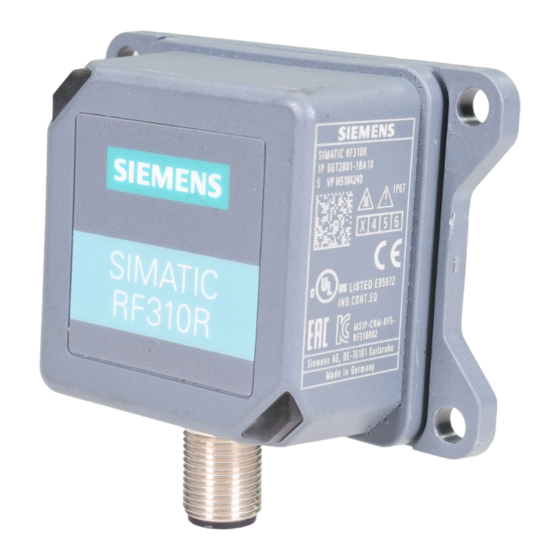
- Page 124 Readers 5.1 SIMATIC RF310R ● MDS-STATUS (mode 3) ● INIT ● REPEAT Special ISO 14443 commands such as "INCREMENT", "DECREMENT" or "SET-VALUE" are not supported. SIMATIC RF310R 5.1.1 Features SIMATIC RF310R Characteristics ① Design RS-422 interface ② Status display Area of application Identification tasks on small assembly lines in harsh industrial environments 5.1.2...
- Page 125 Readers 5.1 SIMATIC RF310R 5.1.3 Pin assignment RF310R with RS-422 interface Assignment Device end 8-pin M12 + 24 V - Transmit + Transmit + Receive - Receive Unassigned Earth (shield) 5.1.4 LED operating display The operational statuses of the reader are displayed by the LEDs. The LED can adopt the colors green, red or yellow and the statuses off , on , flashing : Table 5- 2...
- Page 126 Readers 5.1 SIMATIC RF310R 5.1.6 Metal-free area The RF310R can be flush-mounted in metal. Allow for a possible reduction in the field data. Figure 5-1 Metal-free area for RF310R To avoid any impact on the field data, the distance a should be ≥ 20 mm. 5.1.7 Minimum distance between RF310R readers RF310R side by side...
- Page 127 Readers 5.1 SIMATIC RF310R RF310R face-of-face ≥ 300 mm Figure 5-3 Face-of-face distance between two RF310Rs 5.1.8 Technical specifications Table 5- 3 Technical specifications of the RF310R reader with RS-422 interface 6GT2801-1AB10 Product type designation SIMATIC RF310R Radio frequencies Operating frequency, rated value 13.56 MHz Electrical data Maximum range...
- Page 128 Readers 5.1 SIMATIC RF310R 6GT2801-1AB10 Color Anthracite • • Recommended distance to metal 0 mm Supply voltage, current consumption, power loss Supply voltage 24 VDC Typical current consumption 50 mA Permitted ambient conditions Ambient temperature During operation -25 to +70 ℃ •...
- Page 129 5.1 SIMATIC RF310R 5.1.9 Approvals FCC information Siemens SIMATIC RF310R (MLFB 6GT2801-1AB10); FCC ID NXW-RF310R This device complies with part 15 of the FCC rules. Operation is subject to the following two conditions: (1) This device may not cause harmful interference, and (2) this device must accept any interference received, including interference that may cause undesired operation.
- Page 130 Readers 5.1 SIMATIC RF310R 5.1.10 Dimension drawing Figure 5-4 Dimension drawing for RF310R Dimensions in mm SIMATIC RF300 System Manual, 07/2017, C79000-G8976-C345-07...
- Page 131 Readers 5.2 SIMATIC RF310R with Scanmode SIMATIC RF310R with Scanmode You will find detailed information on the SIMATIC RF310R with Scanmode on the Internet (https://support.industry.siemens.com/cs/ww/en/ps/15034). 5.2.1 Features SIMATIC RF310R special version Characteristics Scanmode ① Design RS-422 interface ② Status display...
- Page 132 Readers 5.2 SIMATIC RF310R with Scanmode 5.2.3 Pin assignment RF310R special version Scanmode RS-422 interface Assignment Device end 8-pin M12 + 24 V - Transmit + Transmit + Receive - Receive Unassigned Earth (shield) 5.2.4 LED operating display The operational statuses of the reader are displayed by the LEDs. The LED can adopt the colors green, red or yellow and the statuses off , on , flashing : Table 5- 5...
- Page 133 Readers 5.2 SIMATIC RF310R with Scanmode 5.2.6 Metal-free area The RF310R special version can be flush-mounted in metal. Allow for a possible reduction in the field data. Figure 5-5 Metal-free area for RF310R special version To avoid any impact on the field data, the distance a should be ≥ 20 mm. 5.2.7 Minimum distance between several readers RF310R special version side by side...
- Page 134 Readers 5.2 SIMATIC RF310R with Scanmode RF310R special version face-to-face ≥ 300 mm Figure 5-7 Face-to-face distance between two RF310R special version 5.2.8 Technical specifications Table 5- 6 Technical specifications of the RF310R reader with Scanmode 6GT2801-1AB20-0AX1 Product type designation SIMATIC RF310R Scanmode Radio frequencies Operating frequency, rated value...
- Page 135 EN 301489, CE, FCC, UL/CSA 5.2.9 Approvals FCC information Siemens SIMATIC RF310R (MLFB 6GT2801-1AB20-0AX1); FCC ID NXW-RF310R This device complies with part 15 of the FCC rules. Operation is subject to the following two conditions: (1) This device may not cause harmful interference, and (2) this device must accept any interference received, including interference that may cause undesired operation.
- Page 136 Readers 5.2 SIMATIC RF310R with Scanmode Note This equipment has been tested and found to comply with the limits for a Class A digital device, pursuant to part 15 of the FCC Rules. These limits are designed to provide reasonable protection against harmful interference when the equipment is operated in a commercial environment.
- Page 137 Readers 5.3 SIMATIC RF310R - 2nd generation SIMATIC RF310R - 2nd generation 5.3.1 Features SIMATIC RF310R Characteristics ① Design RS-422 interface ② LED operating display Area of application Identification tasks on small assembly lines in harsh industrial environments 5.3.2 Ordering data Table 5- 7 RF310R ordering data Article number...
- Page 138 Readers 5.3 SIMATIC RF310R - 2nd generation 5.3.3 Pin assignment of the RS-422 interface Table 5- 8 Pin assignment Assignment Device end 8-pin M12 + 24 V - Transmit + Transmit + Receive - Receive Unassigned Earth (shield) 5.3.4 LED operating display The operational statuses of the reader are displayed by two LEDs.
- Page 139 Readers 5.3 SIMATIC RF310R - 2nd generation 5.3.5 Ensuring reliable data exchange The "center point" of the transponder must be situated within the transmission window. 5.3.6 Metal-free area The RF310R can be flush-mounted in metal. Allow for a possible reduction in the field data. To avoid any influence on the field data, the distance "a"...
- Page 140 Readers 5.3 SIMATIC RF310R - 2nd generation 5.3.7 Minimum distance between RF310R readers RF310R side by side D ≥ 150 mm (with 2 readers) D ≥ 200 mm (with more than 2 readers) Figure 5-10 Minimum distance between RF310R readers RF310R face-of-face D ≥...
- Page 141 Readers 5.3 SIMATIC RF310R - 2nd generation 5.3.8 Technical specifications Table 5- 10 Technical specifications of the RF310R reader with RS-422 interface 6GT2801-1BA10 Product type designation SIMATIC RF310R Radio frequencies Operating frequency, rated value 13.56 MHz Electrical data Maximum range 60 mm Maximum data transmission speed RF300...
- Page 142 Ex approval 5.3.9 Approvals FCC information Siemens SIMATIC RF310R (MLFB 6GT2801-1BA10); FCC ID NXW-RF310R02 This device complies with part 15 of the FCC rules. Operation is subject to the following two conditions: (1) This device may not cause harmful interference, and (2) this device must accept any interference received, including interference that may cause undesired operation.
- Page 143 Readers 5.3 SIMATIC RF310R - 2nd generation Operation of this equipment in a residential area is likely to cause harmful interference in which case the user will be required to correct the interference at his own expense. IC information This device complies with Industry Canada licence-exempt RSS standard(s). Operation is subject to the following two conditions: (1) This device may not cause interference, and (2) this device must accept any interference, including interference that may cause...
- Page 144 Readers 5.3 SIMATIC RF310R - 2nd generation 5.3.10 Dimension drawing Figure 5-12 Dimension drawing for RF310R Dimensions in mm 5.3.11 Using the reader in hazardous area WARNING Explosion hazard In a flammable or combustible environment, no cables may be connected to or disconnected from the device.
- Page 145 Readers 5.3 SIMATIC RF310R - 2nd generation ATEX The SIMATIC Ident products meet the requirements of explosion protection acc. to ATEX. The products meet the requirements of the standards: Document Title EN 60079-0 Hazardous areas Part 0: Equipment - General requirements EN 60079-7 Hazardous areas Part 7: Equipment protection by increased safety "e"...
- Page 146 Readers 5.3 SIMATIC RF310R - 2nd generation IECEx The SIMATIC Ident products meet the requirements of explosion protection acc. to IECEx. The products meet the requirements of the standards: Document Title IEC 60079-0 Hazardous areas Part 0: Equipment - General requirements IEC 60079-7 Hazardous areas Part 7: Equipment protection by increased safety "e"...
- Page 147 Readers 5.3 SIMATIC RF310R - 2nd generation UL HAZ. LOC. The SIMATIC Ident products meet the requirements of explosion protection acc. to UL HAZ. LOC. The products meet the requirements of the standards: Document Title UL 60079-0 Hazardous areas Part 0: Equipment - General requirements CSA C22.2 NO.
- Page 148 Readers 5.3 SIMATIC RF310R - 2nd generation 5.3.11.1 Using the reader in hazardous area for gases The temperature class of the reader for hazardous areas depends on the ambient temperature range: Ambient temperature range Temperature class -25 ℃ ... +70 ℃ WARNING Ignitions of gas-air mixtures When using the reader, check to make sure that the temperature class is adhered to in...
- Page 149 Readers 5.3 SIMATIC RF310R - 2nd generation 5.3.11.3 Installation and operating conditions for hazardous areas: NOTICE Risk of explosion Risk of explosion of dust-air mixtures or gas-air mixtures and the device can be damaged. Note the following conditions when installing and operating the device in a hazardous area: •...
- Page 150 Readers 5.4 SIMATIC RF340R/RF350R SIMATIC RF340R/RF350R 5.4.1 SIMATIC RF340R 5.4.1.1 Features SIMATIC RF340R Characteristics ① Design RS-422 interface ② Status display Area of application Identification tasks on assembly lines in harsh industrial environments 5.4.1.2 Ordering data for RF340R Table 5- 11 Ordering data for RF340R Article number RF340R with RS-422 interface (3964R)
Need help?
Do you have a question about the SIMATIC Ident RF340R02 and is the answer not in the manual?
Questions and answers