Juniper SRX300 Hardware Manual
Hide thumbs
Also See for SRX300:
- Reference manual (142 pages) ,
- Hardware manual (134 pages) ,
- User manual (128 pages)
Table of Contents
Advertisement
Quick Links
Advertisement
Table of Contents
Troubleshooting

Related Manuals for Juniper SRX300


Summary of Contents for Juniper SRX300
- Page 1 SRX300 Firewall Hardware Guide Published 2023-08-15...
- Page 2 The Juniper Networks product that is the subject of this technical documentation consists of (or is intended for use with) Juniper Networks software. Use of such software is subject to the terms and conditions of the End User License Agreement ("EULA") posted at https:/ /support.juniper.net/support/eula/.
-
Page 3: Table Of Contents
SRX300 Firewall Electrical Wiring Guidelines | 16 SRX300 Firewall Grounding Specifications | 18 SRX300 Firewall Physical Specifications | 19 SRX300 Firewall Clearance Requirements for Airflow and Hardware Maintenance | 20 Rack Requirements | 20 Cabinet Requirements | 21 SRX300 Transceiver Specifications and Pinouts | 22... - Page 4 Powering Off the SRX300 Services Gateway | 40 Connecting the SRX300 to External Devices | 41 Connecting the Dial-Up Modem to the Console Port on the SRX300 Services Gateway | 41 Connecting to the SRX300 Firewall CLI Using a Dial-Up Modem | 42...
- Page 5 Customize the Configuration for Junos OS Release 19.2 | 51 Customize the Configuration for Junos OS Release 15.1X49-D170 | 52 Configure the Device Using ZTP with Juniper Networks Network Service Controller | 53 Maintaining Components Maintaining the SRX300 Components | 56...
- Page 6 Product Disposal Warning | 86 Action to Take After an Electrical Accident | 87 General Electrical Safety Guidelines and Warnings | 87 SRX300 Agency Approvals and Compliance Statements | 88 SRX300 Firewall Agency Approvals | 88 SRX300 Firewall EMC Requirements | 90...
-
Page 7: About This Guide
Use this guide to install hardware and perform initial software configuration, routine maintenance, and troubleshooting for the SRX300 Firewall. After completing the installation and basic configuration procedures covered in this guide, refer to the Junos OS documentation for information about further software configuration. -
Page 8: Overview
C HAPTER Overview SRX300 Firewall Overview | 2 SRX300 Chassis | 3 SRX300 Power System | 9... -
Page 9: Srx300 Firewall Overview
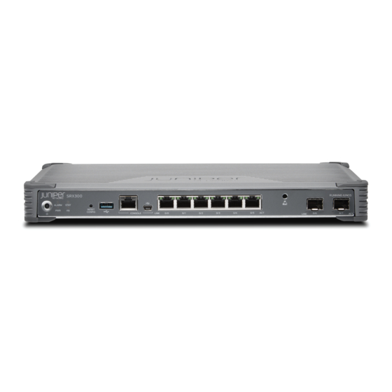
The SRX300 Firewall provides firewall support with key features such as IP security (IPsec) VPN and Content Security . With a desktop form-factor chassis, the SRX300 Firewall has eight 1 G Ethernet ports, two 1 G SFP ports, 4 GB of DRAM memory, and 8 GB of flash memory. -
Page 10: Srx300 Chassis
Understanding the SRX300 Firewall Back Panel | 8 SRX300 Firewall Chassis Overview The SRX300 Firewall chassis weighs 4.38 lb. and measures 1.37 in. high, 12.63 in. wide, and 7.52 in. deep. CAUTION: Before removing or installing components of a functioning services gateway, attach an electrostatic discharge (ESD) strap to an ESD point and place the other end of the strap around your bare wrist. -
Page 11: Understanding The Srx300 Firewall Front Panel
Understanding the SRX300 Firewall Front Panel IN THIS SECTION Network Port LEDs | 7 Figure 1 on page 4 shows the front panel of the SRX300 Firewall. Figure 1: SRX300 Firewall Front Panel Table 1 on page 4 provides details about the front panel components. - Page 12 (Continued) Table 1: SRX300 Firewall Front Panel Components Number Component Description 1-GbE Ethernet ports Six LAN ports (0/0 to 0/5) The ports have the following characteristics: • Use an RJ-45 connector • Operate in full-duplex and half-duplex modes • Support autonegotiation The ports can be used to: •...
- Page 13 (Continued) Table 1: SRX300 Firewall Front Panel Components Number Component Description Mini-USB console port Connects a laptop to the services gateway for CLI management through a USB interface. The port accepts a Mini-B type USB cable plug. A USB cable with Mini-B and Type A USB plugs is supplied with the services gateway.
- Page 14 Table 2 on page 7 lists the front panel LEDs. Table 2: SRX300 Firewall Front Panel LEDs Component Description ALARM • Solid amber (noncritical alarm) • Solid red (critical alarm) • Off (no alarms) STAT • Solid green (operating normally) •...
-
Page 15: Understanding The Srx300 Firewall Back Panel
• Off—There is no link activity. Understanding the SRX300 Firewall Back Panel Figure 3 on page 8 shows the back panel of the SRX300 Firewall and Table 4 on page 8 lists the back panel components. Figure 3: SRX300 Firewall Back Panel... -
Page 16: Srx300 Power System
Understanding the SRX300 Firewall Power Supply The power supply for the SRX300 Firewall is external. You must use the AC to DC, 60 W power supply adapter provided by Juniper Networks to provide power to the services gateway. The adapter provides... -
Page 17: Srx300 Firewall Power Specifications And Requirements
Powering Off the SRX300 Services Gateway | 40 SRX300 Firewall Power Specifications and Requirements Table 5 on page 10 lists the power specifications for the SRX300 Firewall power supply adapter. Table 5: Power Specifications for the SRX300 Firewall Power Supply Adapter Power Supply Adapter Requirement... -
Page 18: Site Planning, Preparation, And Specifications
C HAPTER Site Planning, Preparation, and Specifications Site Preparation Checklist for the SRX300 Firewall | 12 SRX300 Site Guidelines and Requirements | 15 SRX300 Transceiver Specifications and Pinouts | 22... -
Page 19: Site Preparation Checklist For The Srx300 Firewall
Site Preparation Checklist for the SRX300 Firewall Table 6 on page 12 provides a checklist of tasks you need to perform when preparing a site for installing the SRX300 Firewall. Table 6: Site Preparation Checklist for SRX300 Firewall Installation Item or Task Additional Performed By... - Page 20 (Continued) Table 6: Site Preparation Checklist for SRX300 Firewall Installation Item or Task Additional Performed By Date Notes Information Verify that your rack meets SRX300 Services the minimum requirements. Gateway Rack- Mounting Requirements and Warnings Rack Installation Preparing the •...
- Page 21 (Continued) Table 6: Site Preparation Checklist for SRX300 Firewall Installation Item or Task Additional Performed By Date Notes Information Preparing the • Verify that the area SRX300 Services selected meets the Gateway for Wall- minimum requirements. Mount Installation • Verify that you have the...
-
Page 22: Srx300 Site Guidelines And Requirements
• Follow the ESD procedures to avoid damaging equipment. Static discharge can cause components to fail completely or intermittently over time. For more information, see Preventing Electrostatic Discharge Damage to the SRX300 Services Gateway. NOTE: The SRX300 Firewall does not include a fan and does not generate any acoustic noise. -
Page 23: Srx300 Firewall Environmental Specifications
SRX300 Firewall Environmental Specifications Table 7 on page 16 provides the required environmental conditions for normal SRX300 Firewall operations. Table 7: Environmental Specifications for the SRX300 Firewall Description Value Altitude No performance degradation up to 10,000 ft (3048 Relative humidity... - Page 24 Table 8: Site Electrical Wiring Guidelines for the SRX300 Firewall Site Wiring Factor Guideline Signaling Limitations To ensure that signaling functions optimally: • Install wires correctly. Improperly installed wires can emit radio interference. • Do not exceed the recommended distances or pass wires between buildings.
-
Page 25: Srx300 Firewall Grounding Specifications
You must install the SRX300 in a restricted-access location and ensure that the chassis is always properly grounded. The SRX300 device has a one-hole protective grounding terminal provided on the chassis. -
Page 26: Srx300 Firewall Physical Specifications
Up to 4 A Grounding lug Ring-type, vinyl-insulated TV14-6R lug or equivalent SEE ALSO Connecting the SRX300 Firewall Grounding Cable | 37 SRX300 Firewall Physical Specifications Table 10 on page 19 lists the physical specifications for the services gateway. Table 10: Physical Specifications for the SRX300 Firewall... -
Page 27: Srx300 Firewall Clearance Requirements For Airflow And Hardware Maintenance
When planning the installation site for the SRX300 Firewall, you need to allow sufficient clearance around the device. Consider the following: • The SRX300 Firewall does not include a fan and uses natural convection cooling. For the operating temperature of the services gateway to be optimal, the airflow around the chassis must be unrestricted. -
Page 28: Cabinet Requirements
Installing the chassis close to the front of the cabinet maximizes the clearance in the rear of the cabinet for critical airflow. • Route and dress all cables to minimize the blockage of airflow to and from the chassis. RELATED DOCUMENTATION SRX300 Installation Overview | 27... -
Page 29: Srx300 Transceiver Specifications And Pinouts
The Hardware Compatibility Tool enables you to search by product, displaying all the transceivers supported on that device, or category, by interface speed or type. The list of supported transceivers for the SRX300 is located at https:/ /apps.juniper.net/hct/product/#prd=SRX300. -
Page 30: Rj-45 Connector Pinouts For The Srx300 Firewall Console Port
(Continued) Table 11: RJ-45 Connector Pinouts for the SRX300 Firewall Ethernet Port Signal BI_DC+ BI_DC BI_DB BI_DD+ BI_DD RJ-45 Connector Pinouts for the SRX300 Firewall Console Port Table 12 on page 23 describes the RJ-45 connector pinouts for the console port. -
Page 31: Mini-Usb Connector Pinouts For The Srx300 Firewall Console Port
Mini-USB Connector Pinouts for the SRX300 Firewall Console Port The SRX300 Firewall has two console ports: an RJ-45 Ethernet port and a mini-USB Type-B port. If your management device (laptop or PC) does not have a DB-9 plug connector pin or an RJ-45 connector pin,... - Page 32 (Continued) Table 13: Mini-USB Type-B Connector Pinouts for the Services Gateway Console Port Signal Cable Color Description Could be not connected (N/C), connected to ground (GND), or used as an attached device presence indicator Black Ground...
-
Page 33: Initial Installation And Configuration
C HAPTER Initial Installation and Configuration SRX300 Installation Overview | 27 Unpacking and Mounting the SRX300 | 29 Connecting the SRX300 to Power | 37 Connecting the SRX300 to External Devices | 41 Configuring Junos OS on the SRX300 | 43... -
Page 34: Srx300 Installation Overview
SRX300 Firewall Autoinstallation Overview | 28 SRX300 Firewall Installation Overview After you have prepared the site for installation and unpacked the SRX300 Firewall, you are ready to install the device. It is important to proceed through the installation process in the following order: 1. -
Page 35: Srx300 Firewall Autoinstallation Overview
SRX300 Firewall Autoinstallation Overview The autoinstallation process begins any time a services gateway is powered on and cannot locate a valid configuration file in the internal flash. Typically, a configuration file is unavailable when a services gateway is powered on for the first time or if the configuration file is deleted from the internal flash. The autoinstallation feature enables you to deploy multiple services gateways from a central location in the network. -
Page 36: Unpacking And Mounting The Srx300
Installing the SRX300 Firewall in a Rack | 33 Unpacking the SRX300 Firewall The SRX300 Firewall is shipped in a cardboard carton and secured with foam packing material. The carton also contains an accessory box and quick-start instructions. To unpack the SRX300 Firewall: 1. -
Page 37: Verifying Parts Received With The Srx300 Firewall
Verifying Parts Received with the SRX300 Firewall The SRX300 Firewall shipment package contains a packing list. Check the parts in the shipment against the items on the packing list. The packing list specifies the part numbers and carries a brief description of each part in your order. -
Page 38: Installing The Srx300 Firewall On A Desk
Installing the SRX300 Firewall on a Desk You can mount an SRX300 Firewall on a desk or any other level surface horizontally or vertically. The four rubber feet attached to the chassis provide stability. Before mounting an SRX300 Firewall on a desk... - Page 39 Figure 5: Orienting the SRX300 Firewall on a Wall 6. Have a second person install two pairs of mounting screws through the bracket holes on either side of the device to secure it to the wall.
-
Page 40: Installing The Srx300 Firewall In A Rack
Installing the SRX300 Firewall in a Rack You can front-mount the SRX300 Firewall in a rack. Many types of racks are acceptable, including four- post (telco) racks, enclosed cabinets, and open-frame racks. For more information about the type of rack... - Page 41 2. Use a number-2 Phillips screwdriver to install the screws that secure the mounting brackets and power supply adapter tray to the chassis as shown in Figure 8 on page Figure 8: SRX300 Firewall Rack Installation — Securing the Mounting Brackets and Power Supply Adapter Tray...
- Page 42 3. Place the power supply adapter in the tray as shown in Figure 9 on page Figure 9: SRX300 Firewall Rack Installation — Positioning the Power Supply Adapter Tray 4. Have one person grasp the sides of the device, lift it, and position it in the rack.
- Page 43 Figure 10: SRX300 Firewall Rack Installation — Positioning the SRX300 Firewall in a Rack 6. Have a second person install a mounting screw into each of the two aligned holes. Tighten the mounting screws. 7. Install the second screw in each mounting bracket.
-
Page 44: Connecting The Srx300 To Power
M4 screw. You must install the SRX300 in a restricted-access location and ensure that the chassis is always properly grounded. The SRX300 device has a single-hole protective grounding terminal provided on the chassis. - Page 45 Figure 11 on page Figure 11: Connecting the Grounding Cable to the SRX300 Firewall 5. Secure the grounding cable lug to the grounding point, first with the washer, then with the screw. Apply between 6 in.-lb (0.67 Nm) and 8 in.-lb (0.9 Nm) of torque to the screw.
-
Page 46: Connecting The Srx300 Firewall To The Power Supply
Figure 12 on page 2. Plug the AC adapter end of the power cable into an AC power outlet. Figure 12: Connecting the SRX300 Firewall to the Power Supply Powering On the SRX300 Services Gateway To power on the services gateway:... -
Page 47: Powering Off The Srx300 Services Gateway
If the device finishes starting and you need to power off the system again, first issue the CLI request system power-off command. Powering Off the SRX300 Services Gateway You can power off the services gateway in one of the following ways: •... -
Page 48: Connecting The Srx300 To External Devices
Connecting the SRX300 to External Devices IN THIS SECTION Connecting the Dial-Up Modem to the Console Port on the SRX300 Services Gateway | 41 Connecting to the SRX300 Firewall CLI Using a Dial-Up Modem | 42 Connecting the Dial-Up Modem to the Console Port on the SRX300... -
Page 49: Connecting To The Srx300 Firewall Cli Using A Dial-Up Modem
JNP-CBL-RJ45-DB9 (DB-9 to RJ-45 adapter with a CAT5E copper cable). Connecting to the SRX300 Firewall CLI Using a Dial-Up Modem To remotely connect to the CLI through a dial-up modem connected to the console port on the services gateway: 1. -
Page 50: Configuring Junos Os On The Srx300
Configure the Device Using ZTP with Juniper Networks Network Service Controller | 53 The services gateway is shipped with the Juniper Networks Junos operating system (Junos OS) preinstalled and ready to be configured when the device is powered on. You can perform the initial software configuration of the services gateway by using the browser-based setup wizard or by using the command-line interface (CLI). -
Page 51: Srx300 Firewall Factory-Default Settings
Security Zone DHCP State IP Address 0/0 and 0/7 ge-0/0/0 and ge-0/0/7 untrust Client Unassigned 0/1 to 0/6 VLAN Interface irb.0 (ge-0/0/1 to ge-0/0/6) trust Server 192.168.1.1/24 The SRX300 device is shipped with the following services and protocols enabled by default. -
Page 52: Initial Configuration Using The Cli
Table 18: Services, Protocols, and Startup Mode Services Protocols Device Startup Mode RSTP (all interfaces) Switching HTTPS NETCONF over SSH To provide secure traffic, a basic set of screens are configured on the untrust zone. How to View Factory-Default Settings To view the factory-default settings on your device: 1. -
Page 53: Connect To The Serial Console Port
2. Plug the RJ-45 to DB-9 serial port adapter into the serial port on the management device. 3. Connect the other end of the Ethernet cable to the serial console port on the SRX300. Figure 13: Connect to the Console Port on the SRX300 4. -
Page 54: Connect To The Mini-Usb Console Port
Click OK when the installation is complete. 3. Plug the large end of the USB cable supplied with the SRX300 into a USB port on the management device. 4. Connect the other end of the USB cable to the mini-USB console port on the SRX300. -
Page 55: Configure The Srx300 Using The Cli
• Stop bits—1 • Flow control—None 7. If you have not already done so, power on the SRX300 by pressing the Power button on the front panel. Verify that the PWR LED on the front panel turns green. The terminal emulation screen on your management device displays the startup sequence. When the SRX300 has finished starting up, a login prompt appears. -
Page 56: Initial Configuration Using J-Web
4. Commit the configuration to activate it on the device. [edit] root# commit Initial Configuration Using J-Web IN THIS SECTION Configure Using J-Web | 49 Customize the Configuration for Junos OS Release 19.2 | 51 Customize the Configuration for Junos OS Release 15.1X49-D170 | 52 Configure Using J-Web To configure the device by using J-Web: 1. - Page 57 Figure 14: Connect the SRX300 to a Management Device The SRX300 functions as a DHCP server and automatically assigns an IP address to the laptop. 3. Ensure that the management device acquires an IP address on the 192.168.1.0/24 network from the device.
-
Page 58: Customize The Configuration For Junos Os Release 19.2
The J-Web login page appears. The SRX300 already has factory-default settings configured to make it a plug-and-play device. So all you have to do to get the SRX300 up and running is connect it to your LAN and WAN networks. -
Page 59: Customize The Configuration For Junos Os Release 15.1X49-D170
You can select any one of the configuration modes to customize the configuration: • Guided Setup (uses a dynamic IP address)—Enables you to set up the SRX300 in a custom security configuration. You can select either the Basic or the Expert option. -
Page 60: Configure The Device Using Ztp With Juniper Networks Network Service Controller
• Default Setup (uses a dynamic IP address)—Enables you to quickly set up the SRX300 with the default configuration. Any additional configuration can be done after the wizard setup is completed. • High Availability—Enables you to set up a chassis cluster with a default basic configuration. - Page 61 Figure 15: Authentication Code Page On successful authentication, the initial configuration is applied and committed on the SRX300. Optionally, the latest Junos OS image is installed on the SRX300 before the initial configuration is applied. • If you do not have the authentication code, you can use the J-Web setup wizard to configure the...
-
Page 62: Maintaining Components
C HAPTER Maintaining Components Maintaining the SRX300 Components | 56... -
Page 63: Maintaining The Srx300 Components
Maintaining the SRX300 Components IN THIS SECTION Routine Maintenance Procedures for the SRX300 Services Gateway | 56 Maintaining the SRX300 Firewall Power Supply | 56 Routine Maintenance Procedures for the SRX300 Services Gateway For optimum performance of the services gateway, perform the following preventive maintenance procedures regularly: •... -
Page 64: Troubleshooting Hardware
C HAPTER Troubleshooting Hardware Troubleshooting the SRX300 | 58... -
Page 65: Troubleshooting The Srx300
IN THIS SECTION Troubleshooting Resources for the SRX300 Firewall Overview | 58 Troubleshooting Chassis and Interface Alarm Messages on the SRX300 Firewall | 59 Troubleshooting the Power System on the SRX300 Services Gateway | 60 Using the RESET CONFIG Button | 61... -
Page 66: Troubleshooting Chassis And Interface Alarm Messages On The Srx300 Firewall
To view a more detailed description of the alarm cause, issue the show chassis alarms CLI command. Table 19 on page 59 describes alarms that can occur for an SRX300 Firewall chassis component. Table 19: SRX300 Firewall Chassis Alarm Conditions and Corrective Actions Component... -
Page 67: Troubleshooting The Power System On The Srx300 Services Gateway
(Continued) Table 19: SRX300 Firewall Chassis Alarm Conditions and Corrective Actions Component Alarm Conditions Action Alarm Severity The services gateway The services gateway shuts down automatically temperature is too high, in 4 minutes. (major) either because of an internal overheating... -
Page 68: Using The Reset Config Button
JTAC. SEE ALSO Troubleshooting Chassis and Interface Alarm Messages on the SRX300 Firewall | 59 Using the RESET CONFIG Button If a configuration fails or denies management access to the services gateway, you can use the RESET CONFIG button to restore the device to the factory-default configuration or a rescue configuration. -
Page 69: Changing The Reset Config Button Behavior
• By default, pressing and quickly releasing the RESET CONFIG button loads and commits the rescue configuration through the J-Web interface or the CLI. The Status LED is solid amber during this time. • By default, pressing and holding the RESET CONFIG button for 15 seconds or more—until the Status LED is solid amber —... -
Page 70: Contacting Customer Support And Returning The Chassis Or Components
C HAPTER Contacting Customer Support and Returning the Chassis or Components Returning the SRX300 Chassis or Components | 64... -
Page 71: Returning The Srx300 Chassis Or Components
Contacting Customer Support Once you have located the serial numbers of the device or component, you can return the device or component for repair or replacement. For this, you need to contact Juniper Networks Technical Assistance Center (JTAC). You can contact JTAC 24 hours a day, 7 days a week, using any of the following methods: •... -
Page 72: Returning A Srx300 Firewall Component To Juniper Networks
Returning a SRX300 Firewall Component to Juniper Networks To return an SRX300 Firewall or component to Juniper Networks for repair or replacement: 1. Determine the part number and serial number of the services gateway or component. -
Page 73: Listing The Srx300 Firewall Component Details With The Cli
Listing the SRX300 Firewall Component Details with the CLI Before contacting Juniper Networks to request an RMA, you must find the serial number on the SRX300 Firewall or component. To list all of the SRX300 Firewall components and their serial numbers, enter the following command: user@host>... -
Page 74: Packing Srx300 Firewall Components For Shipment
12. Write the Return Materials Authorization (RMA) number on the exterior of the box to ensure proper tracking. Packing SRX300 Firewall Components for Shipment Follow these guidelines for packing and shipping individual components of the services gateway: • When you return a component, make sure that it is adequately protected with packing materials and packed so that the pieces are prevented from moving around inside the carton. -
Page 75: Safety And Compliance Information
Jewelry Removal Warning | 83 Operating Temperature Warning | 84 Product Disposal Warning | 86 Action to Take After an Electrical Accident | 87 General Electrical Safety Guidelines and Warnings | 87 SRX300 Agency Approvals and Compliance Statements | 88... -
Page 76: Definitions Of Safety Warning Levels
Definitions of Safety Warning Levels Warning formats): The documentation uses the following levels of safety warnings (there are two NOTE: You might find this information helpful in a particular situation, or you might overlook this important information if it was not highlighted in a Note. CAUTION: You need to observe the specified guidelines to prevent minor injury or discomfort to you or severe damage to the device. -
Page 77: General Safety Guidelines And Warnings
Warnung Dieses Warnsymbol bedeutet Gefahr. Sie befinden sich in einer Situation, die zu einer Körperverletzung führen könnte. Bevor Sie mit der Arbeit an irgendeinem Gerät beginnen, seien Sie sich der mit elektrischen Stromkreisen verbundenen Gefahren und der Standardpraktiken zur Vermeidung von Unfällen bewußt. Avvertenza Questo simbolo di avvertenza indica un pericolo. - Page 78 • Do not wear loose clothing or jewelry, such as rings, bracelets, or chains, which could become caught in the device. • Wear safety glasses if you are working under any conditions that could be hazardous to your eyes. • Do not perform any actions that create a potential hazard to people or make the equipment unsafe. •...
-
Page 79: Restricted Access Warning
Restricted Access Warning WARNING: This unit is intended for installation in restricted access areas. A restricted access area is an area to which access can be gained only by service personnel through the use of a special tool, lock and key, or other means of security, and which is controlled by the authority responsible for the location. -
Page 80: Qualified Personnel Warning
que possua uma ferramenta, chave e fechadura especial, ou qualquer outra forma de segurança. Esta área é controlada pela autoridade responsável pelo local. ¡Atención! Esta unidad ha sido diseñada para instalarse en áreas de acceso restringido. Área de acceso restringido significa un área a la que solamente tiene acceso el personal de servicio mediante la utilización de una herramienta especial, cerradura con llave, o algún otro medio de seguridad, y que está... -
Page 81: Prevention Of Electrostatic Discharge Damage
¡Atención! Estos equipos deben ser instalados y reemplazados exclusivamente por personal técnico adecuadamente preparado y capacitado. Varning! Denna utrustning ska endast installeras och bytas ut av utbildad och kvalificerad personal. Prevention of Electrostatic Discharge Damage Device components that are shipped in antistatic bags are sensitive to damage from static electricity. Some components can be impaired by voltages as low as 30 V. -
Page 82: Fire Safety Requirements
Figure 16: Placing a Component into an Antistatic Bag CAUTION: ANSI/TIA/EIA-568 cables such as Category 5e and Category 6 can get electrostatically charged. To dissipate this charge, always ground the cables to a suitable and safe earth ground before connecting them to the system. Attention Les câbles ANSI/TIA/EIA-568, par exemple Cat 5e et Cat 6, peuvent emmagasiner des charges électrostatiques. - Page 83 NOTE: To keep warranties effective, do not use a dry chemical fire extinguisher to control a fire at or near a Juniper Networks device. If a dry chemical fire extinguisher is used, the unit is no longer eligible for coverage under a service agreement.
-
Page 84: Laser And Led Safety Guidelines And Warnings
Class 1 LED Product Warning | 78 Laser Beam Warning | 79 Juniper Networks devices are equipped with laser transmitters, which are considered a Class 1 Laser Product by the U.S. Food and Drug Administration and are evaluated as a Class 1 Laser Product per IEC/EN 60825-1 requirements. - Page 85 Class 1 Laser Product Warning LASER WARNING: Class 1 laser product. Waarschuwing Klasse-1 laser produkt. Varoitus Luokan 1 lasertuote. Avertissement Produit laser de classe I. Warnung Laserprodukt der Klasse 1. Avvertenza Prodotto laser di Classe 1. Advarsel Laserprodukt av klasse 1. Aviso Produto laser de classe 1.
-
Page 86: Radiation From Open Port Apertures Warning
Laser Beam Warning LASER WARNING: Do not stare into the laser beam or view it directly with optical instruments. Waarschuwing Niet in de straal staren of hem rechtstreeks bekijken met optische instrumenten. Varoitus Älä katso säteeseen äläkä tarkastele sitä suoraan optisen laitteen avulla. Avertissement Ne pas fixer le faisceau des yeux, ni l'observer directement à... -
Page 87: Battery-Handling Warning
Varoitus Koska portin aukosta voi emittoitua näkymätöntä säteilyä, kun kuitukaapelia ei ole kytkettynä, vältä säteilylle altistumista äläkä katso avoimiin aukkoihin. Avertissement Des radiations invisibles à l'il nu pouvant traverser l'ouverture du port lorsqu'aucun câble en fibre optique n'y est connecté, il est recommandé de ne pas regarder fixement l'intérieur de ces ouvertures. - Page 88 aanbevolen is. Gebruikte batterijen dienen overeenkomstig fabrieksvoorschriften weggeworpen te worden. Varoitus Räjähdyksen vaara, jos akku on vaihdettu väärään akkuun. Käytä vaihtamiseen ainoastaan saman- tai vastaavantyyppistä akkua, joka on valmistajan suosittelema. Hävitä käytetyt akut valmistajan ohjeiden mukaan. Attention Danger d'explosion si la pile n'est pas remplacée correctement. Ne la remplacer que par une pile de type semblable ou équivalent, recommandée par le fabricant.
-
Page 89: Lightning Activity Warning
Lightning Activity Warning WARNING: Do not work on the system or connect or disconnect cables during periods of lightning activity. Waarschuwing Tijdens onweer dat gepaard gaat met bliksem, dient u niet aan het systeem te werken of kabels aan te sluiten of te ontkoppelen. Varoitus Älä... -
Page 90: Jewelry Removal Warning
Jewelry Removal Warning WARNING: Before working on equipment that is connected to power lines, remove jewelry, including rings, necklaces, and watches. Metal objects heat up when connected to power and ground and can cause serious burns or weld the metal object to the terminals. -
Page 91: Operating Temperature Warning
To prevent airflow restriction, allow at least 6 in. (15.2 cm) of clearance around the ventilation openings. Waarschuwing Om te voorkomen dat welke services gateway van de Juniper Networks services gateway dan ook oververhit raakt, dient u deze niet te bedienen op een plaats ο... - Page 92 ο C. Ettei ilmanvaihto estyisi, tuuletusaukkojen ympärille on jätettävä ainakin 15,2 cm tilaa. Attention Pour éviter toute surchauffe des routeurs de la gamme Juniper Networks services gateway, ne l'utilisez pas dans une zone où la température ambiante est ο supérieure à 40 C.
-
Page 93: Product Disposal Warning
RELATED DOCUMENTATION Battery-Handling Warning | 80 Lightning Activity Warning | 82 Jewelry Removal Warning | 83 Product Disposal Warning | 86 Product Disposal Warning WARNING: Disposal of this product must be handled according to all national laws and regulations. Waarschuwing Dit produkt dient volgens alle landelijke wetten en voorschriften te worden afgedankt. -
Page 94: Action To Take After An Electrical Accident
RELATED DOCUMENTATION Battery-Handling Warning | 80 Lightning Activity Warning | 82 Jewelry Removal Warning | 83 Operating Temperature Warning | 84 Action to Take After an Electrical Accident If an electrical accident results in an injury, take the following actions in this order: 1. -
Page 95: Srx300 Agency Approvals And Compliance Statements
In Case of Electrical Accident AC Power Electrical Safety Guidelines SRX300 Agency Approvals and Compliance Statements IN THIS SECTION SRX300 Firewall Agency Approvals | 88 SRX300 Firewall EMC Requirements | 90 SRX300 Firewall Agency Approvals IN THIS SECTION Compliance Statement for Argentina | 90... - Page 96 • Safety • CAN/CSA-C22.2 No.60950-1 (2007) Information Technology Equipment • UL 60950-1 (2nd Ed.) Information Technology Equipment • EN 60950-1 (2006+ A11:2010) Information Technology Equipment - Safety • IEC 60950-1 (2005 +A1:2009) Information Technology Equipment - Safety (All country deviations): CB Scheme report •...
-
Page 97: Srx300 Firewall Emc Requirements
• Telco • Common Language Equipment Identifier (CLEI) code Compliance Statement for Argentina EQUIPO DE USO IDÓNEO. SEE ALSO SRX300 Firewall EMC Requirements | 90 SRX300 Firewall EMC Requirements IN THIS SECTION Canada | 91 European Community | 91 Israel | 91... - Page 98 Canada This Class A digital apparatus complies with Canadian ICES-003. Cet appareil numérique de la classe A est conforme à la norme NMB-003 du Canada. European Community This is a Class A product. In a domestic environment this product may cause radio interference in which case the user may be required to take adequate measures.
- Page 99 when the equipment is operated in a commercial environment. This equipment generates, uses, and can radiate radio frequency energy and, if not installed and used in accordance with the instruction manual, may cause harmful interference to radio communications. Operation of this equipment in a residential area is likely to cause harmful interference in which case the user will be required to correct the interference at his own expense.
Need help?
Do you have a question about the SRX300 and is the answer not in the manual?
Questions and answers