Table of Contents
Advertisement
Advertisement
Table of Contents

Subscribe to Our Youtube Channel
Related Manuals for Xylem Flygt Top 50


Summary of Contents for Xylem Flygt Top 50
- Page 1 Installation, Operation, and Maintenance Manual 894192_14.0 Flygt Top...
-
Page 3: Table Of Contents
Table of Contents Table of Contents 1 Introduction and Safety......................3 1.1 Introduction........................3 1.2 Safety terminology and symbols..................3 1.3 User safety........................4 1.4 Special hazards......................4 1.4.1 Confined spaces..................... 4 1.4.2 Biological hazards....................4 1.4.3 Wash the skin and eyes..................5 1.5 Protecting the environment....................5 1.6 Spare parts........................ - Page 4 Table of Contents 4.2.9 Equipotential bonding................... 16 4.2.10 Backfill.........................16 4.2.11 Installing the access cover in vehicular traffic areas...........17 4.3 Install the pump......................18 5 Operation........................... 20 5.1 Precautions........................20 5.2 Before commissioning....................20 5.3 Start the pump......................21 6 Maintenance........................22 6.1 Precautions........................22 6.1.1 Inspect the work area before permit-required hot work........
-
Page 5: Introduction And Safety
This includes any modification to the equipment or use of parts not provided by Xylem. If there is a question regarding the intended use of the equipment, please contact a Xylem representative before proceeding. -
Page 6: User Safety
1 Introduction and Safety Electrical hazard Magnetic fields hazard Electrical Hazard: CAUTION: 1.3 User safety All regulations, codes, and health and safety directives must be observed. The site • Observe lockout and tagout procedures before starting work on the product, such as transportation, installation, maintenance, or service. -
Page 7: Wash The Skin And Eyes
• Clean-up of spills Exceptional sites CAUTION: Radiation Hazard Do NOT send the product to Xylem if it has been exposed to nuclear radiation, unless Xylem has been informed and appropriate actions have been agreed upon. 1.6 Spare parts CAUTION: Only use the manufacturer’s original spare parts to replace any worn or faulty components. -
Page 8: Transportation And Storage
2 Transportation and Storage 2 Transportation and Storage 2.1 Precautions DANGER: Electrical Hazard Before starting work on the unit, make sure that the unit and the control panel are isolated from the power supply and cannot be energized. This applies to the control circuit as well. CAUTION: The operator must be aware of safety precautions to prevent physical injury. -
Page 9: Transportation Guidelines
2 Transportation and Storage 2.4 Transportation guidelines 2.4.1 Lifting Always inspect the lifting equipment and tackle before starting any work. WARNING: Crush Hazard Always lift the unit by its designated lifting points. Use suitable lifting equipment and ensure that the product is properly harnessed. Wear personal protective equipment. -
Page 10: Long-Term Storage
2 Transportation and Storage Figure 3: Lifting eyes for sling b) Lift the unit straight up. The unit may jolt or sway near the end of the lifting operation. WARNING: Crush Hazard Always lift the unit by its designated lifting points. Use suitable lifting equipment and ensure that the product is properly harnessed. -
Page 11: Product Description
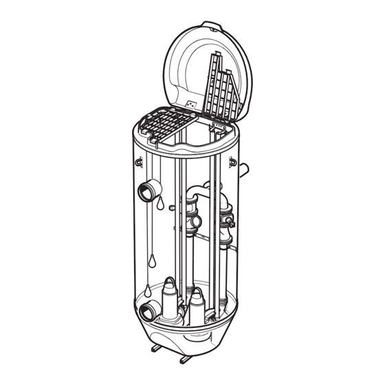
3 Product Description 3 Product Description 3.1 Products included This document includes the following products: • Top 50, 9050.010 • Top 65, 9065.010 • Top 80, 9080.010 • Top 100S, 9100.010 • Top 150S, 9150.010 • Top 150L, 9150.020 3.2 Design The pump station unit is delivered complete with prefabricated inlet and outlet pipe connections and a connection for an overflow pipe, if ordered. -
Page 12: Application Limits
3 Product Description 3.2.3 Application limits For pump limitations, read the Installation, Operation, and Maintenance manual for the pump. The unit must be installed underground, outside of the building. Data Description Media (liquid) temperature Maximum 40°C (104°F) pH of the pumped media 5.5–9 Unit depth Maximum 6 m (20 ft) -
Page 13: External Loads
3 Product Description Polymer resin The thermosetting resin that is used is unsaturated polyester and phenyl acrylate (vinyl ester) resins of commercial grade. Glass fiber reinforcement The reinforcing material is glass fiber of a grade that complies with the technical requirements of the application. -
Page 14: Installation
4 Installation 4 Installation 4.1 Precautions Introduction and Before starting work, make sure that the safety instructions in the chapter Safety on page 3 have been read and understood. DANGER: Inhalation Hazard The chamber or tank where the equipment is installed should be treated as a confined space. -
Page 15: Inspect The Work Area Before Permit-Required Hot Work
4 Installation Figure 6: Bracing and shoring Figure 7: Shield box • Regularly check the walls of an excavation or trench for cracks, bulges and spalling. Check the shoring for signs of distress, especially after a rainstorm. • Do not work in an excavation that is filled or partially filled with water. Remove personnel from the excavation during a rainstorm, and inspect the excavation carefully before re- entry. -
Page 16: Prepare The Pit Base
4 Installation Top version Ø (mm) 150S 2900 150L 3200 4.2.2 Prepare the pit base • Check that the pit bottom is even before preparing the base. • Check that the base is flat, evenly compacted, and horizontally leveled before installing the unit. -
Page 17: Connect The External Piping
4 Installation Table 4: Required dimensions for concrete footing TOP version Minimum diameter F, Approximated concrete Height h: Minimum - volume, m Maximum, mm 100 S 2100 1.2 -1.6 450–550 150 S 2300 1.5–2.0 450–550 150 L 2600 2.0–2.5 450–550 Filling the unit with water up to a height of minimum 1500 mm (4.9 ft) gives sufficient counterweight during casting. -
Page 18: Install The Control Panel
4 Installation Use applicable support grips. 2. Adjust the height of the level sensors according to the installation drawing. NOTICE: It is essential to ensure the proper functioning of level regulators in the unit. 4.2.8 Install the control panel 1. Run the cables through the cable entry to the start and control panel. The pump motor cable must be long enough to enable removal of the pump from the unit. -
Page 19: Installing The Access Cover In Vehicular Traffic Areas
4 Installation Table 5: Physical properties of backfill material Physical property Requirement Grain size, diameter 0.06–20 mm (0.002–0.79 in) Organic content < 2% by weight Content of grains sized <0.06 mm (0.002 in) <15% by weight Uniformity coefficient, CU = d 5–10 Water content, w 3–8%... -
Page 20: Install The Pump
4 Installation Concrete slab design 1. Concrete slab 2. Concrete ring stiffener 3. Ground level 4. Flexible sealing 5. Backfill Recommended minimum dimensions 1. Pump 2. Slab Pump type Circular Ø mm Rectangular (L x W) mm • C/D 3057 600 x 350 •... - Page 21 4 Installation 1. Lower the pump along the guide bars. On reaching the bottom position, the pump automatically connects to the pre-assembled discharge connection. The pump can be hoisted up along the guide bars for inspection without undoing any connection. 2.
-
Page 22: Operation
5 Operation 5 Operation 5.1 Precautions Before taking the unit into operation, check the following: • All recommended safety devices are installed. • The cable and cable entry have not been damaged. • All debris and waste material has been removed. NOTICE: Never operate the pump with the discharge line blocked, or the discharge valve closed. -
Page 23: Start The Pump
5 Operation 5.3 Start the pump Follow the instructions in the Installation, Operation, and Maintenance manual for the pump and the control panel. 1. Open the shutoff valve. 2. Switch on the main power supply. 3. Check that the unit is emptied from water: a) Fill the tank with water up to the start level. -
Page 24: Maintenance
6 Maintenance 6 Maintenance 6.1 Precautions Introduction and Before starting work, make sure that the safety instructions in the chapter Safety on page 3 have been read and understood. DANGER: Inhalation Hazard Before entering the work area, make sure that the atmosphere contains sufficient oxygen and no toxic gases. -
Page 25: Inspect The Work Area Before Permit-Required Hot Work
6 Maintenance • Do not stand directly over the cover to open it. Stand to the side. Wait at least five minutes after opening, to let any fumes disperse, before approaching the hole. • Never work alone. 5’ Figure 11: Waiting five minutes after opening, to let fumes disperse 6.1.1 Inspect the work area before permit-required hot work WARNING: Explosion/Fire Hazard Before starting any permit-required hot work such as welding, gas cutting, grinding, or using... - Page 26 6 Maintenance 4. Clean the level regulators by removing any sediments deposited. 5. Wash the inlet pump housing with generous amounts of water. 6. Check the condition of the impeller. 7. Flush the wall tanks, pipes and accessories that have been in contact with the pumped media with generous amounts of water.
-
Page 27: Declaration Of Conformity
NO Xylem Water Solutions Norge AS, Oslo, Norway, Tel. +47-22-90 16 00 PT Xylem Water Solutions Portugal Lda. Barca - Maia, Portugal, Tel. +351 229 478 550 PO Xylem Water Solutions Polska Sp. z o.o, Raszyn, Poland, Tel. +48-22-735 81 00 SE Xylem Water Solutions Sweden AB, Sundbyberg, Sweden, Tel. - Page 28 For more information on how Xylem can help you, go to www.xylem.com Xylem Water Solutions Global Visit our Web site for the latest version of this document...
Need help?
Do you have a question about the Flygt Top 50 and is the answer not in the manual?
Questions and answers