Table of Contents
Advertisement
Quick Links
Chapter 1 ____________________________________ Introduction
Chapter 2 ___________________________________ Specification
Chapter 3 _____________________________ Product Description
Chapter 4 _____________________________________ Installation
Chapter 5 _____________________________ Operating Procedure
Chapter 6 _____________________________ In Case of a Problem
Appendix A ______________________________ Setup Data Sheets
Appendix B _______________________________ Mounting Details
Appendix C ______________________ Electrical Interface Diagram
AMS Controls
5/23/2012
Closed Loop Backgauge Controller
1
Model
MP328CL
Reference Manual
MP328CL Controller
Gripper
Advertisement
Table of Contents

Subscribe to Our Youtube Channel
Related Manuals for AMS Controls MP328CL


Summary of Contents for AMS Controls MP328CL
- Page 1 Chapter 4 _____________________________________ Installation Chapter 5 _____________________________ Operating Procedure Chapter 6 _____________________________ In Case of a Problem Appendix A ______________________________ Setup Data Sheets Appendix B _______________________________ Mounting Details Appendix C ______________________ Electrical Interface Diagram AMS Controls MP328CL Controller 5/23/2012 Gripper...
- Page 2 The MP328CL is housed in a compact 8.00” x 12.50” wide x 2.25” deep enclosure and requires a single 24 VDC power supply for operation.
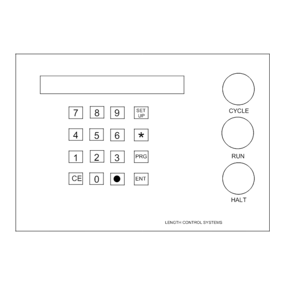
- Page 3 Front Panel Components and Description The Model MP328CL front panel has three push button switches, a 16 key keypad, and a two line 48 character liquid crystal display. The three push buttons provide the following functions: • CYCLE This push button will open the gripper jaws and will reset the sequence •...
-
Page 4: Reference Mode
The SETUP mode is used when the MP328CL is initially installed to configure it to the particular characteristics of the Gripper. The SETUP mode is entered by pressing the “Set Up” key and the mode can be exited by pressing the “∗” key. When power is applied to the controller, the built-in diagnostics check the memory for data retention. - Page 5 NOTE: If the LOOP ENABLE input is used while the brake is activated, the LOOP ENABLE input must be reactivated before the total BRAKE DWELL (down and up) is completed. AMS Controls MP328CL Controller 5/23/2012 Gripper...
- Page 6 This parameter should be kept as close to zero as possible to give the controller the maximum control range. AMS Controls MP328CL Controller 5/23/2012 Gripper...
- Page 7 The TOLERANCE should be set small enough to get acceptable parts but wide enough to avoid production interruptions. The controller allows values from 0.0005 inches to 10.0000 inches. The default value for TOLERANCE is 1.0000 inches. AMS Controls MP328CL Controller 5/23/2012 Gripper...
- Page 8 4) Use the following formula for the new CORRECTION FACTOR, using the average of the ten parts for "actual measured position.": New CORR. FACTOR = (Programmed Length ÷ Actual Measured Position) x Old CORR. FACTOR AMS Controls MP328CL Controller 5/23/2012 Gripper...
- Page 9 If “2” is pressed, the INPUT/OUTPUT screen can be viewed. Out: _ _ 3 _ _ _ _ _ This can be helpful as a troubleshooting aid if the machine is not working properly. AMS Controls MP328CL Controller 5/23/2012 Gripper...
- Page 10 Near referencing with a home switch: 1. The MP328CL determines the state of the Home Switch. If the switch is OPEN, skip to step # 3. 2. The MP328CL moves the gauge in the forward direction until the Home Switch is OPEN.
- Page 11 NOTES: • If near referencing is used, the home switch must be wired N/C (normally closed). Far referencing requires that normally open contacts be used. AMS Controls MP328CL Controller 5/23/2012 Gripper...
-
Page 12: Program Mode
After the TYPE is selected, the HEIGHT and WIDTH measurements can then be entered. Again use the “ENT” key to lock the selection in. Only height will be used for (-) type parts. PROGRAM SCREEN 0.00” Type : 0 50.00” 35.00” AMS Controls MP328CL Controller 5/23/2012 Gripper... -
Page 13: Status Screen
(wait for the dwell time), then move to the next position. When all bends are made, it should return to the clearance position (as programmed in the configuration). AMS Controls MP328CL Controller 5/23/2012 Gripper... - Page 14 The clearance position of the gripper should be far enough away so that it will not interfere with the operator AMS Controls MP328CL Controller 5/23/2012 Gripper...
- Page 15 As soon as the gripper “sees” the metal, it clamps. Because of this arrangement, it is necessary to feed the metal only a short distance. AMS Controls MP328CL Controller 5/23/2012 Gripper...
- Page 16 Encoder Direction Not Used Must be OFF Unit ID Must be OFF The proper Unit ID switch setting for the MP328CL is: switches 2 and 3 ON. Some systems have the capability of having 2 MP328CLs, and the Unit ID switch setting for the second controller is: switches 1, 2, and 3 ON.
-
Page 17: Mounting Details
Mounting Details Figure B-1. Panel Mount Mounting Dimensions AMS Controls MP328CL Controller 5/23/2012 Gripper...
Need help?
Do you have a question about the MP328CL and is the answer not in the manual?
Questions and answers