Table of Contents
Advertisement
Quick Links
Advertisement
Table of Contents

Related Manuals for TechVision PBS8P3WZ-I/A


Summary of Contents for TechVision PBS8P3WZ-I/A
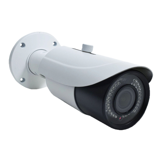
- Page 1 PBS8P3WZ-I/A 8MP IP Motorized Bullet...
- Page 2 Notes on Safety Notes This product is intended to be supplied by a Listed Power Unit, marked with 'Limited Power Source', 'LPS' on unit, output rated minimum 12V/2 A or POE 48V/ 350mA or AC24V (depending on models), no more than 2000m altitude of operation and Tma=60 Deg.C.
- Page 3 Disclaimer With regard to the product with internet access, the use of product shall be wholly at your own risks. Our company shall be irresponsible for abnormal operation, privacy leakage or other damages resulting from cyber attack, hacker attack, virus inspection, or other internet security risks;...
-
Page 4: Table Of Contents
Table of Contents Introduction ........................1 Network Connection ...................... 2 LAN ..............................2 2.1.1 Access through IP-Tool ....................2 2.1.2 Direct Access through IE ....................4 WAN ............................... 5 Live View ........................8 Network Camera Configuration ................. 11 System Configuration........................11 4.1.1 Basic Information ...................... - Page 5 Network Camera User Manual 4.6.4 DDNS ........................... 45 4.6.5 SNMP ........................... 46 4.6.6 802.1x ........................... 47 4.6.7 RTSP ..........................48 4.6.8 UPNP ........................... 49 4.6.9 Email ..........................50 4.6.10 FTP ..........................51 4.6.11 HTTPS.......................... 51 4.6.12 P2P (Optional) ......................53 4.6.13 QoS..........................
-
Page 6: Introduction
Network Camera User Manual 1 Introduction This IP-CAMERA (short for IP-CAM) is designed for high performance CCTV solutions. It adopts state of the art video processing chips, integrated with the most advanced technologies (like video encoding and decoding technology) to make the image transmission more stable and smooth. -
Page 7: Network Connection
Network Camera User Manual 2 Network Connection Connect IP-CAM via LAN or WAN. Here only take IE browser for example. The details are as follows: 2.1 LAN In LAN, there are two ways to access IP-CAM: 1. access through IP-Tool; 2. direct access through IE browser. - Page 8 Network Camera User Manual For example, the IP address of your computer is 192.168.1.4. So the IP address of the camera shall be changed to 192.168.1.X. After modification, please enter the password of the administrator and click “Modify” to modify the settings. ...
-
Page 9: Direct Access Through Ie
Network Camera User Manual The system will prompt the above-mentioned textbox to ask you to change the default password. It is strongly recommended to change the default password for account security. If “Do not show again” is checked, the textbox will not be prompted next time. 2.1.2 Direct Access through IE The default network settings are as shown below: IP address: 192.168.226.201... -
Page 10: Wan
Network Camera User Manual ② Open the IE browser and enter the default address of IP-CAM and confirm. ③ Follow directions to download and install the Active X control. ④ Enter the default username and password in the login window and then enter to view. 2.2 WAN ... - Page 11 Network Camera User Manual IP Setup ③ Go to the router’s management interface through IE browser to forward the IP address and port of the camera in the “Virtual Server”. Router Setup ④ Open the IE browser and enter its WAN IP and http port to access. (for example, if the http port is changed to 81, please enter “192.198.1.201:81”...
- Page 12 Network Camera User Manual ① Go to ConfigNetworkPort menu to set the port number. ② Go to Config NetworkTCP/IPPPPoE Config menu. Enable PPPoE and then enter the user name and password from your internet service provider. ③ Go to Config NetworkDDNS menu. Before configuring the DDNS, please apply for a domain name first.
-
Page 13: Live View
Network Camera User Manual 3 Live View After logging in, the following window will be shown. The following table is the instructions of the icons on the live view interface. Icon Description Icon Description Original size SD card recording indicator Fit correct scale Color abnormal indicator Auto (fill the window) - Page 14 Network Camera User Manual Icon Description Icon Description Zoom in People intrusion indicator Zoom out Sensor alarm indicator PTZ control Motion alarm indicator AZ control (only available model with Face detection indicator motorized zoom lens ) Those smart alarm indicators will flash only when the camera supports those functions and the corresponding events are enabled.
- Page 15 Network Camera User Manual Auto scan Wiper Light Radom scan Group scan Preset Select preset and click to call the preset. Select and set the preset and then click save the position of the preset. Select the set preset and click to delete it.
-
Page 16: Network Camera Configuration
Network Camera User Manual 4 Network Camera Configuration In the Webcam client, choose “Config” to go to the configuration interface. Note: Wherever applicable, click “Save” to save the settings. 4.1 System Configuration 4.1.1 Basic Information In the “Basic Information” interface, the system information of the device is listed. Some versions may support device ID and QR code. -
Page 17: Local Config
Network Camera User Manual Click the “Date and Time” tab to set the time mode. 4.1.3 Local Config Go to ConfigSystemLocal Config to set up the storage path of captured pictures and recorded videos on the local PC. There is also an option to enable or disable the bitrate display in the recorded files. - Page 18 Network Camera User Manual Snapshot Quota: Set the capacity proportion of captured pictures on the SD card. Video Quota: Set the capacity proportion of record files on the SD card. Schedule Recording Settings 1. Go to Config System Storage Record to go to the interface as shown below.
-
Page 19: Image Configuration
Network Camera User Manual Day schedule Set the alarm time for alarm a special day, such as a holiday. Note: Holiday schedule takes priority over weekly schedule. Snapshot Settings Go to Config System Storage Snapshot to go to the interface as shown below. Set the format, resolution and quality of the image saved on the SD card and the snapshot interval and quantity and the timing snapshot here. - Page 20 Network Camera User Manual effect can be quickly seen by switching the configuration file. Brightness: Set the brightness level of the camera’s image. Contrast: Set the color difference between the brightest and darkest parts. Hue: Set the total color degree of the image. Saturation: Set the degree of color purity.
-
Page 21: Video / Audio Configuration
Network Camera User Manual BLC: If enabled, the auto exposure will activate according to the scene so that the object of the image in the darkest area will be seen clearly. Antiflicker: Off: disables the anti-flicker function. This is used mostly in outdoor installations. ... - Page 22 Network Camera User Manual frame rate, bitrate type, video quality and so on subject to the actual network condition. Click the “Audio” tab to go to the interface as shown below. Three video streams can be adjustable. Resolution: The size of image. Frame rate: The higher the frame rate, the video is smoother.
-
Page 23: Osd Configuration
Network Camera User Manual Watermark: When playing back the local recorded video in the search interface, the watermark can be displayed. To enable it, check the watermark box and enter the watermark text. Audio Encoding: G711A and G711U are selectable. Audio Type: LIN or MIC optional. -
Page 24: Roi Configuration
Network Camera User Manual To set up video mask: 1. Enable video mask. 2. Click “Draw Area” and then drag the mouse to draw the video mask area. 3. Click “Save” to save the settings. 4. Return to the live to verify that the area have been drawn as shown as blocked out in the image. -
Page 25: Lens Control
Network Camera User Manual 1. Check “Enable” and then click “Draw Area” button. 2. Drag the mouse to set the ROI area. 3. Set the level. 4. Click “Save” to save the settings. 4.2.6 Lens Control This function is only available for the model with motorized zoom lens. Within this section, zoom and focus can be controlled. -
Page 26: Ptz Configuration
Network Camera User Manual 4.3 PTZ Configuration This function is only available for the models with RS485 interface. It can be used with a compatible external PTZ enclosure. Go to PTZProtocol interface as shown below. Set the protocol, address and baud rate according to the PTZ. 4.4 Alarm Configuration 4.4.1 Motion Detection Go to AlarmMotion Detection to set motion detection alarm. - Page 27 Network Camera User Manual 1. Check “Enable” check box to activate motion based alarms. If unchecked, the camera will not send out any signals to trigger motion-based recording to the NVR or CMS, even if there is motion in the video. Alarm Out: If selected, this would trigger an external relay output that is connected to the camera on detecting a motion based alarm.
-
Page 28: Other Alarms
Network Camera User Manual Move the “Sensitivity” scroll bar to set the sensitivity. Higher sensitivity value means that motion will be triggered more easily. Select “Add” and click “Draw”. Drag the mouse to draw the motion detection area; Select “Erase” and drag the mouse to clear motion detection area. After that, click the “Save”... - Page 29 Network Camera User Manual 2. Click “Enable” and set the alarm holding time. 3. Set alarm trigger options. Trigger alarm out, Email and FTP. The setup steps are the same as motion detection. Please refer to motion detection chapter for details. ...
-
Page 30: Alarm In
Network Camera User Manual 2. Click “Enable” and set the alarm holding time. 3. Trigger alarm out. When the camera is disconnected, the system will trigger the alarm out. 4.4.3 Alarm In This function is only available for some models. To set sensor alarm (alarm in): Go to ConfigAlarmAlarm In interface as shown below. - Page 31 Network Camera User Manual Alarm Out Mode: Alarm linkage, manual operation, day/night switch linkage and timing are optional. Alarm Linkage: Having selected this mode, select alarm out name and alarm holding time at the “Alarm Holding Time” pull down list box. Manual Operation: Having selected this mode, select the alarm type and click “Open”...
-
Page 32: Alarm Server
Network Camera User Manual 4.4.5 Alarm Server Go to AlarmAlarm Server interface as shown below. Set the server address, port, heartbeat and heartbeat interval. When an alarm occurs, the camera will transfer the alarm event to the alarm server. If an alarm server is not needed, there is no need to configure this section. - Page 33 Network Camera User Manual 1. Enable object removal detection and then select the detection type. Enable Left Detection: Alarms will be triggered if there are items left in the pre-defined area. Enable Item Missing Detection: Alarms will be triggered if there are items missing in the pre-defined area.
-
Page 34: Exception
Network Camera User Manual can be added. Click “Draw Area” and then click around the area where you want to set as the alarm area in the image (the alarm area should be a closed area). Click “Stop Draw” to stop drawing. - Page 35 Network Camera User Manual 1. Enable the applicable detection that’s desired. Scene Change Detection: Alarms will be triggered if the scene of the monitor video has changed. Video Blur Detection: Alarms will be triggered if the video becomes blurry. Enable Video Color Cast Detection: Alarms will be triggered if the video becomes obscured.
-
Page 36: Line Crossing
Network Camera User Manual The sensitivity value of Video Color Cast Detection: The higher the value is, the more sensitive the system responds to the obscuring of the image. ※ The requirements of camera and surrounding area 1. Auto-focusing function should not been enabled for exception detection. 2. - Page 37 Network Camera User Manual Set the alarm line number and direction. Up to 4 lines can be added. Multiple lines cannot be added simultaneously. Direction:A<->B, A->B and A<-B optional. This indicates the direction of the intruder who crosses over the alarm line that would trigger the alarm. A<->B: The alarm will be triggered when the intruder crosses over the alarm line from B to A or from A to B.
-
Page 38: Intrusion
Network Camera User Manual There are so many trees near the road and cars running on the road, which make the scene too complex to detect the crossing objects. The ground is covered with vegetation; at the right of the fence is a gym where people pass by frequently. - Page 39 Network Camera User Manual 1. Enable region intrusion detection alarm and set the alarm holding time. 2. Set alarm trigger options. The setup steps are the same as motion detection. Please refer to motion detection chapter for details. 3. Click “Save” to save the settings. 4.
-
Page 40: Crowd Density Detection
Network Camera User Manual ※ Configuration requirements of camera and surrounding area 1. Auto-focusing function should not be enabled for intrusion detection. 2. Avoid the scenes with many trees or the scenes with various light changes (like many flashing headlights). The ambient brightness of the scenes shouldn’t be too low. 3. - Page 41 Network Camera User Manual 1. Enable the crowd density detection. 2. Set “Refresh Frequency”, “Density Alarm Threshold” and “Alarm Holding Time”. Refresh Frequency: The refresh frequency of the detection result. Density Alarm Threshold: Alarms will be triggered once the percentage of the crowd density in a specified area exceeds the pre-defined threshold value.
-
Page 42: People Intrusion
Network Camera User Manual 5. Set the schedule of the crowd density detection. The setup steps of the schedule are the same as schedule recording setup (See Schedule Recording). ※Configuration of camera and surrounding area 1. The camera lens should face to the people flow. The direction of the people flow is allowed to deviate slightly from the direction of the camera lens (The angle (a) shall be less than 45°... -
Page 43: People Counting
Network Camera User Manual 1. Go to ConfigEventPeople Intrusion. Please refer to the following picture. 2. Enable the people intrusion detection. 3. Set “Alarm Sensitivity” and “Alarm Holding Time”. 4. Set alarm trigger options. The setup steps are the same as motion detection setup. Please refer to motion detection chapter for details. - Page 44 Network Camera User Manual 2. Enable the people counting detection. 3. Set “Detection Sensitivity”, “Entrancing Threshold”, “Departing Threshold”, “Staying Threshold”, “Counting Period”, “Alarm Holding Time” and so on. Counting Period: All, daily, weekly and monthly are optional. Counting Reset: The current number of people counting will be cleared and the current counting period will restart by clicking “Reset”...
- Page 45 Network Camera User Manual Click “Draw Area” and drag the mouse to draw a rectangle area. Drag the four boundary lines Click “Draw Area” and drag the mouse to draw a rectangle area. Drag the four border lines or the four corners of the rectangle to modify its size. Click “Stop Draw” to stop drawing the area.
-
Page 46: Face Detection
Network Camera User Manual head of a single person should account for about 1/5 of the height of the entire image. Remember keeping a certain space on both sides to let the entrance/exit lie in the center of the entire image. The recommending height of installation as shown below: Lens Mounting height... - Page 47 Network Camera User Manual 3. Set alarm detection area. Max. detection face Min. detection face These face contours will change as the set minimum and maximum value. Click “Draw Area” and drag the border lines of the rectangle to modify its size. Move the rectangle to change its position.
-
Page 48: Network Configuration
Network Camera User Manual 4. Set the schedule of the face detection. The setup steps of the schedule are the same as schedule recording setup (See Schedule Recording). ※ Configuration requirements of camera and surrounding area 1. Cameras must be installed in the area with stable and adequate light sources. 2. -
Page 49: Port
Network Camera User Manual address automatically by DHCP and use the following IP address. Please choose one of the options as needed. Test: Test the effectiveness of the IP address by clicking this button. Use PPPoE-Click the “PPPoE Config” tab to go to the interface as shown below. Enable PPPoE and then enter the user name and password from your ISP. -
Page 50: Server Configuration
Network Camera User Manual occupied. Data Port: The default data port is 9008. It can be changed to any port which is not occupied. RTSP Port: The default port is 554. It can be changed to any port which is not occupied. 4.6.3 Server Configuration This function is mainly used for connecting network video management system. -
Page 51: Snmp
Network Camera User Manual Create domain name. After the domain name is successfully applied for, the domain name will be listed as below. 3. Enter the username, password, domain you apply for in the DDNS configuration interface. 4. Click “Save” to save the settings. 4.6.5 SNMP To get camera status, parameters and alarm information and remotely manage the camera, the SNMP function can be used. -
Page 52: 802.1X
Network Camera User Manual 2. Check the corresponding version checkbox (Enable SNMPv1, Enable SNMPv2, Enable SNMPv3) according to the version of the SNMP software that will be used. 3. Set the values for “Read SNMP Community”, “Write SNMP Community”, “Trap Address”, “Trap Port”... -
Page 53: Rtsp
Network Camera User Manual To use this function, the camera shall be connected to a switch supporting 802.1x protocol. The switch can be reckoned as an authentication system to identify the device in a local network. If the camera connected to the network interface of the switch has passed the authentication of the switch, it can be accessed via the local network. -
Page 54: Upnp
Network Camera User Manual Select “Enable” to enable the RTSP function. Port: Access port of the streaming media. The default number is 554. RTSP Address: The RTSP address (unicast) format that can be used to play the stream in a media player. -
Page 55: Email
Network Camera User Manual Go to ConfigNetworkUPnP. Enable UPNP and then enter UPnP name. 4.6.9 Email If you need to trigger Email when an alarm happens or IP address is changed, please set the Email here first. Go to ConfigNetwork Email. Sender Address: Sender’s e-mail address. -
Page 56: Ftp
Network Camera User Manual and multiple motion detection alarms are triggered within 60 seconds, they will be considered as only one alarm event and only one email will be sent. If one motion alarm event is triggered and then another motion detection alarm event is triggered after 60 seconds, two emails will be sent. - Page 57 Network Camera User Manual There is a certificate installed by default as shown above. Enable this function and save it. Then the camera can be accessed by entering https://IP: https port via the web browser (eg. https://192.168.226.201:443). A private certificate can be created if users don’t want to use the default one. Click “Delete” to cancel the default certificate.
-
Page 58: P2P (Optional)
Network Camera User Manual Click “Create” to create the certificate request. Then download the certificate request and submit it to the trusted certificate authority for signature. After receiving the signed certificate, import the certificate to the device. 4.6.12 P2P (Optional) If this function is enabled, the network camera can be quickly accessed by adding the device ID in mobile surveillance client or CMS/NVMS client via WAN. - Page 59 Network Camera User Manual 2. Enter user name in “User Name” textbox. 3. Enter letters or numbers in “Password” and “Confirm Password” textbox. 4. Choose the user type. Administrator has all permissions. Normal user can only view the live video. Advanced user has the same permissions as an Administrator except for user, backup settings, factory reset, and upgrading the firmware.
-
Page 60: Online User
Network Camera User Manual Delete user: 1. Select the user to be deleted in the user configuration list box. 2. Click the “Delete” button to delete the user. Note: The default administrator account cannot be deleted. 4.7.2 Online User Go to ConfigSecurityOnline User to view the user who is viewing the live video. An administrator user can kick out all the other users (including other administrators). -
Page 61: Maintenance Configuration
Network Camera User Manual For some specified versions, anonymous login with a private protocol can be enabled here. If this function is enabled, enter http://host:port/Anonymous/1[2/3] (eg. http://192.168.226.201:80/Anonymous/1) via web browser to access the camera. 1 indicates main stream; 2 indicates sub stream; 3 indicates third stream. Only video can be viewed by this means and no other operations can be done. -
Page 62: Upgrade
Network Camera User Manual Timed Reboot Setting: If necessary, the camera can be set up to reboot on a time interval. Enable “Time Settings”, set the date and time and then click “Save” to save the settings. 4.8.3 Upgrade Go to ConfigMaintenanceUpgrade. In this interface, the camera firmware can be updated. -
Page 63: Search
Network Camera User Manual 5 Search 5.1 Image Search Click Search to go to the interface as shown below. Local Image Search Choose “Picture”—“Local”. Set time: Select date and choose the start and end time. Click to search the images. Double click a file name in the list to view the captured photos as shown above. - Page 64 Network Camera User Manual Click to return to the previous interface. SD Card Image Search Images that are saved on the SD card can be found here. Note: If there is no SD card installed in the camera or the SD card is not compatible with the camera, a pop-up message will show stating that there is no card.
-
Page 65: Video Search
Network Camera User Manual Icon Description Icon Description Slide show play: Click this Stop: Click this button to stop the button to start the slide show slide show. mode. Play speed: Play speed of the slide show. 5.2 Video Search 5.2.1 Local Video Search Click Search to go to the interface as shown below. -
Page 66: Sd Card Video Search
Network Camera User Manual Icon Description Icon Description Play button. After pausing the video, click this button Pause button to continue playing. Stop button Speed down Speed up Watermark display Enable / disable audio; drag the slider to adjust the volume after enabling audio. - Page 67 Network Camera User Manual Select the alarm events at the bottom of the interface. Select mix stream (video and audio stream) or video stream as needed. Double click on a file name in the list to start playback. The time table can be shown in 24H/12H/2H/1H format by clicking the corresponding buttons.
- Page 68 Network Camera User Manual Click “Set up” to set the storage directory of the video files. Click “Open” to play the video. Click “Clear List” to clear the downloading list. Click “Close” to close the downloading window.
-
Page 69: Appendix
Network Camera User Manual Appendix Appendix 1 Troubleshooting How to find the password? A:Reset the device to the default factory settings. Default IP: 192.168.226.201; User name: admin; Password: 123456 Fail to connect devices through IE browser. A: Network is not well connected. Check the connection and make sure it is connected well. B: IP address is not available. - Page 70 Network Camera User Manual No sound can be heard. A:Audio input device is not connected. Please connect and try again. B: Audio function is not enabled at the corresponding channel. Please enable this function.
Need help?
Do you have a question about the PBS8P3WZ-I/A and is the answer not in the manual?
Questions and answers