Advertisement
Quick Links
Variants:
7031021999
7031321009
7031321999
7047021009
7047021099
7047021159
7047021244
7047021249
Content:
Function diagram
Description DMS module
Description display module
Cabelplan
Cableplan
Description of faults
Calibration (lin.)
Replacement
PC configuration program
Spare parts Display
Spare parts baseframe
Spare parts baseframe Mod. 703 DMS high end
Manual number:
17-05-01-325-d
Service Manual
for seca 703 / 704 CN
Description:
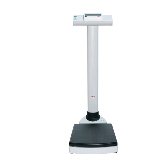
calibratable scale based on a DMS platform - load cell
703 : Columnscale kg, lbs, sts digital, battery connection, optional with measuring
rod.
704 : Columnscale calibrated kg, Battery connection
Service Manual Number
17-05-01-325-d
Valid as of:
25-01-02-584
30-34-00-645 b
30-34-00-618 a
08-02-06-032 a
08-02-06-035 a
30-34-00-588 c
30-34-00-603
30-34-00-720
30-34-00-672 b
30-34-00-717 b
30-34-00-719 c
30-34-00-736 b
01.12.2010
Advertisement

Related Manuals for Seca 703 CN


Summary of Contents for Seca 703 CN
- Page 1 Service Manual Variants: for seca 703 / 704 CN 7031021999 7031321009 7031321999 7047021009 Service Manual Number 7047021099 7047021159 17-05-01-325-d 7047021244 Valid as of: 01.12.2010 7047021249 Description: calibratable scale based on a DMS platform - load cell 703 : Columnscale kg, lbs, sts digital, battery connection, optional with measuring rod.
- Page 3 EEPROM is integrated which is used to configure the module. A connection to the SeSAM bus (Seca’s Serial Autoconfiguring Multicontroller bus) is provided via which the scale can be calibrated and additional modules can be connected.
- Page 4 Service manual Description of the electronics Display (only DMS low-end module and SLC highend) Whenever eight new measured values are available, i.e. approx. every 0.8 s, the weight is displayed. The display is an LCD which is controlled by duplex operation. A maximum of five digits as well as a few special characters can be displayed.
- Page 5 Service manual Description of the electronics If the start button is directly connected to this interrupt input, a button is obtained which is only active when the scale is switched off. It can be fitted under the platform, for instance, so that the scale is started by briefly stepping on it.
- Page 6 Service manual Description of the electronics Time base From the quartz’s 4.19MHz a time base is derived which controls all timed processes in the scale. These are, for instance, various timeouts and the on-time. After expiry of the on-time, the supply voltage for the analog part, for voltage measurement and for the EEPROM is switched off.
- Page 7 Service manual Description of the electronics Technical data Supply voltage: Load cell voltage + 0.5 V to 15 V Supply current: approximate load cell current Zero-signal current: typ. 2µA Operating temperature: approx. 0°C to 50°C Storage temperature: -10°C to 60°C 05.08.03 /Jensen / Rei 34-34-00-645 b...
- Page 8 Brief description of the display module Introduction The display modules belong to the family of seca electronic modules and are used to display a weight measured with a suitable module and transferred via the SeSAM bus (Seca’s Serial Autoconfiguring Multicontroller bus). Furthermore, the display modules accommodate the operating elements and can process the weight (hold, tare, etc.).
- Page 9 Power supply Power supply is provided via the SeSAM bus. Operation With the exception of a start button that might be available, the connected buttons can be configured as required for the particular model. These buttons can be pressed just lightly or longer (longer than 1.5s).
- Page 10 Recalibration In order to compensate for linear measuring errors of the scale, which can, for instance, occur as a result of the different forces of gravity at different geographical points, the module has a recalibration function. To initiate the function, another button must be pressed when the scale is started. The verification counter is then displayed which is incremented whenever the scale is recalibrated.
- Page 11 Technical data Supply voltage: 2.7V - 3V and 2.7V - 15V (via SeSAM bus) Supply current: typ. 0.5mA + power supply for backlighting (typ. 100mA) Quiescent current: typ. 2µA Operating temperature: approx. 0°C to 50°C Storage temperature: -10°C to 60°C Dimensions: 74mm x 50mm x 23mm small display...
- Page 14 Service manual Description of faults Please refer to the operating instructions to ensure that the scales were operated in the proper Please refer to the operating instructions to ensure that the scales were operated in the proper Please refer to the operating instructions to ensure that the scales were operated in the proper Please refer to the operating instructions to ensure that the scales were operated in the proper manner.
- Page 15 Service manual Description of faults Description of the Possible Remedy fault cause • • • Er:x:11 Sensor is Check connection cables, check sensor and replace as required defective or (if parts a replaced, a recalibration is necessary) supply lines • If several load cell are used, check the allocation (colour codes) are damaged •...
- Page 16 General: General: Seca scales with modular electronics are fitted with a software-controlled calibration device that is operated using the existing controls. This device can be used to recalibrate the scales or to set the scales to different GAL values. During development of the calibration device, special attention was paid to the following requirements: •...
- Page 17 Vogel & Halke File: 00603_e1.doc seca Created on: 30.06.1998 Printed on: 07.07.1999 Holger Panier / SE Pressing the kg/lbs key for less than 1.5 seconds causes the weight shown on the display to be increased or decreased by 10 g (depending on the mode currently selected). As the resolution of the display is lower, the displayed value will not necessarily be increased or decreased each time the kg/lbs key is pressed.
- Page 18 Vogel & Halke File: 00603_e1.doc seca Created on: 30.06.1998 Printed on: 07.07.1999 Holger Panier / SE Summary of a typical recalibration sequence: Summary of a typical recalibration sequence: Action carried out by the user Result The scales are switched off.
- Page 19 Service Manual Replacement instructions seca 703 / 704 CN Removing the power supply Before starting any work unplug the mains plug and remove the batteries! ESD protection measures must be taken whenever work is performed on electronic components. 1. Opening the scale When replacing - platform load cell "P", DMS –...
- Page 20 Service Manual Replacement instructions 2.4 Replacing display board "AP", membrane keyboard "FT" and battery connection "BA" (page 4) Unscrew the 4 M6 countersunk screws "C1" from the side covers. Unsolder the cable connections from the parts to be replaced. Display board "AP": Slacken the four fixing screws "P2" and detach the plug "S3" of the cable connection from the bottom part.
- Page 23 Service manual Spare parts list seca 703 / 704 CN Display Item Articel no: Designation price stage 34-02-00-018-509 Displayhousing compl. without electronic 34-02-01-226-807 Profile 34-02-01-216-807 Operating housing left 34-02-04-342-009 Membrane keyboard mod. 703/704 34-02-04-372-009 Membrane keyboard mod. 704 China 34-02-04-370-009 Membrane keyboard mod.
- Page 25 Service manual Spare parts list seca 703 704 / 763 / 764 CN effective until ser. no.:. 5703317062328, Baseframe Item Articel No.: Designation Price stage 08-06-12-234-009 Load cell Mod. 703 effective until ser. No. :. 5703317062327 Mod. 704/763/764 02-03-03-293-009 Cross beam for plattform 08-06-18-084-009 DMS –Basic Modul...
- Page 27 Service manual Spare parts list seca 703 DMS high end CN effective from ser. No. 5703317062328 Item. Articel No.: Designation Price stage 02-02-03-298-009 Frame 01-12-02-002-009 Roller compl.. with axle and holder 02-02-03-295-816 Column connection 08-06-16-136-119 Harness mains connection compl 01-13-05-398-807 Plug mod.
Need help?
Do you have a question about the 703 CN and is the answer not in the manual?
Questions and answers