Advertisement
Quick Links
Variants:
7177021008
7177021098
7177021248
7577021004
7577021094
Description:
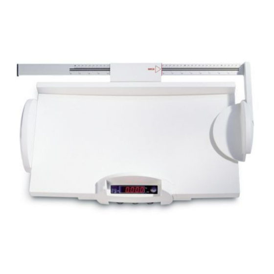
High resolution approved baby scale with integrated LED-display
Content:
Operation
Operation
Operation
Function diagram
Function diagram
Electronics
Block diagram electronics
Description of faults
Replacement
Calibration
spare parts
Manual number:
17-05-01-249-f
Service Manual
for seca
717A, 717 Japan, 757
Service Manual Number:
17-05-01-249-f
Valid as of:
Valid until:
17-10-07-314
c
17-10-07-345
b
17-10-07-354
25-01-02-446
d
25-01-02-503
25-01-02-467
e
08-09-01-267
c
30-34-00-437
g
30-34-00-483
e
30-34-00-609
30-34-00-550
f
30.08.00
Advertisement

Related Manuals for Seca 717A


Summary of Contents for Seca 717A
- Page 1 Service Manual for seca 717A, 717 Japan, 757 Variants: 7177021008 7177021098 7177021248 7577021004 Service Manual Number: 7577021094 17-05-01-249-f Valid as of: 30.08.00 Valid until: Description: High resolution approved baby scale with integrated LED-display Content: Operation 17-10-07-314 Operation 17-10-07-345 Operation 17-10-07-354...
- Page 4 In order to ensure a higher signal yield for the For temperature compensation of the strain gauge seca 717, the measuring element and the A/D sensor, a fixed-value resistor is connected in converter are supplied with 10V; usually, a 5V parallel with a temperature-dependent resistor.
- Page 5 If the bottom or upper limit of the A/D converter is overshot, "EEEEE" is displayed. Zero point determination After starting, "SECA" is displayed for approx. 1 Range switch-over for model 717 second. During this period, the zero point is By pressing the weighing range switch-over determined.
- Page 6 5V voltage. setting. For the seca 717, the 10V in-phase regulator 451 Power supply is used which supplies the A/D converter and the The circuit has the following special features: force measuring element using buffer capacitors 452, 453.
- Page 7 Circuit description Model 717,727,728,737,748,757 Blatt 4(3) Diode 102 is used as polarity reversal protection and overvoltage protection. Diodes 110 and 111 protect against discharge during battery operation and against polarity reversal. Electrolytic and tantalum capacitors are distributed evenly over the printed circuit board as backup capacitors for the operating voltage.
- Page 9 Seca 717/727/728/737/748/757 Description of faults short positive pulse must be registered. If there Troubleshooting is no pulse, check the start button and diodes First and foremost make a visual inspection, 115 and 118, otherwise replace IC 126. checking the soldering points and for corrosion Measure the voltage at pin 1 of IC 131.
- Page 10 On seca 748, the voltage at capacitor 120 must be approx. 9 V, on seca 727 and seca 757 it must be approx. 7.2 V. If the voltage is different, recharge or replace the rechargeable battery.
- Page 11 Check the slope and adjust if necessary, see manual adjustment instructions: seca 727: No. 30-34-00-448 seca 737/757: No. 30-34-00-484 seca 748: No. 30-34-00-446 9. Fault description: Scale displays "EEEE" after starting Check fuse 450 or soldering jumper 450 and replace if necessary.
- Page 12 Description of faults Model 748 Check the force sensor connection: Check the cables between the main board and Check the soldered connections (for seca 748 the supplementary board: see drawing 08-06-04-541). - Check the soldered connections - Measure the signals 5V, GND, REF, TEST on...
- Page 13 1.1 to 4.1. 5.2 Adjust and check the scale in accordance with the instructions for manual calibration or adjustment. seca 727/728: 30-34-00-484, 30-34-00-336 seca 717/737/757: 30-34-00-484,30-34-00-4 5.3 Calibrate the scale. (Only applies for model 717/737/757) 08.01.98-Ha. Blatt 1 (2)
- Page 14 Model 717 Adjustment Instruction Procedure to adjust the scale model 717: 1) Place the scale on a smooth ground and align it by means of a level device. Pay attention that the scale is adapted to the environment temperature prior to the adjustment. 1) Connect the scale with the supply unit to the power supply.
- Page 15 717A,717 japan, 757 Spare parts list seca 717A, 757 Item Article no. Designation Price stage 02-01-01-252-008 Frame black 01-10-04-007-509 Levelling device 08-06-14-239-009 Battery compartment 08-04-05-336-009 PCB holder 08-06-16-058-119 Cable harness for rechargeable battery connection (model 757 only) 08-06-16-083-119 Cabel harness for RS 232 interface (model 757 only )
- Page 16 717A,717 japan, 757 Spare parts list Item Article no. Designation Price stage 02-03-01-254-009 Baby tray (model 717 only) 01-22-13-310-009 Front plate (model 717/717 Japan) 01-22-13-294-009 Front plate (model 757 only) 68-22-12-721-009 Set of rechargeable batteries Ni-MH 7.2 V /1100 mAh...
Need help?
Do you have a question about the 717A and is the answer not in the manual?
Questions and answers