Table of Contents
Advertisement
Quick Links
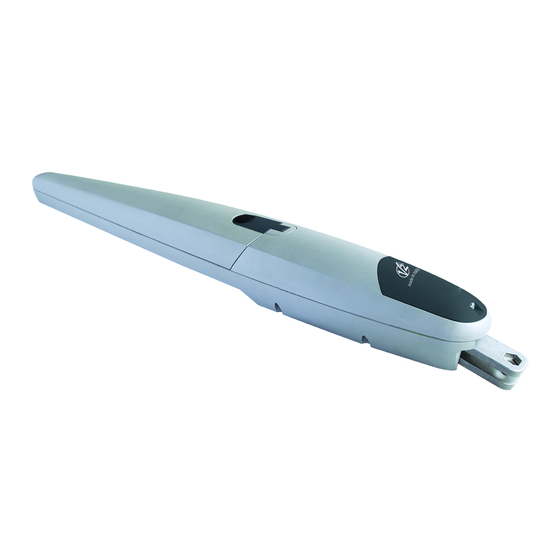
STARK6
I
ATTUATORE ELETTROMECCANICO
IRREVERSIBILE PER CANCELLI A
BATTENTE
GB
IRREVERSIBLE
ELECTROMECHANICAL
ACTUATOR FOR SWING GATES
F
OPERATEUR ELECTROMECANIQUE
IRREVERSIBLE POUR
PORTAILS BATTANTS
E
OPERADOR ELECTROMECÁNICO
IRREVERSIBLE PARA
CANCELAS BATIENTES
D
NICHT UMKEHRBARER
ELEKTROMECHANISCHER
ANTRIEB FÜR FLÜGELTORE
NL
ELEKTROMECHANISCHE,
ONOMKEERBARE LINEAIRE
MOTOR VOOR HEKKEN MET
VLEUGELS
PL
ELEKTROMECHANICZNY
NIEODWRACALNY SIŁOWNIK DO
BRAM SKRZYDŁOWYCH
ZIS549
EDIZ. 01/09/2022
Advertisement
Table of Contents

Related Manuals for V2 STARK6


Summary of Contents for V2 STARK6
- Page 1 ZIS549 EDIZ. 01/09/2022 STARK6 ATTUATORE ELETTROMECCANICO NICHT UMKEHRBARER IRREVERSIBILE PER CANCELLI A ELEKTROMECHANISCHER BATTENTE ANTRIEB FÜR FLÜGELTORE IRREVERSIBLE ELEKTROMECHANISCHE, ELECTROMECHANICAL ONOMKEERBARE LINEAIRE ACTUATOR FOR SWING GATES MOTOR VOOR HEKKEN MET VLEUGELS OPERATEUR ELECTROMECANIQUE ELEKTROMECHANICZNY IRREVERSIBLE POUR NIEODWRACALNY SIŁOWNIK DO PORTAILS BATTANTS BRAM SKRZYDŁOWYCH...
- Page 2 1030...
-
Page 3: Important Remarks
The standards require a separation of the contacts of at least 3 mm in each pole (EN 60335-1). V2 has the right to modify the product without previous • The plastic case has an IP44 insulation; to connect flexible or notice;... - Page 4 PRELIMINARY CHECKS AND IDENTIFICATION OF THE TYPE TO BE USED It should be remembered that the device does not compensate for defects caused by improper installation, or poor maintenance, thus, prior to proceeding with installation, ensure that the structure is suitable and meets current standards and, if necessary, perform any structural modifications aimed at the implementation of safety gaps and the protection or segregation of all crushing, shearing and transit zones, and verify that: •...
-
Page 5: Use Limitations
EU DECLARATION OF CONFORMITY The relevant technical documentation is available at the national authorities’ request after justifiable request to: AND DECLARATION OF V2 S.p.A., Corso Principi di Piemonte 65, 12035, Racconigi (CN), INCORPORATION OF PARTLY Italia COMPLETED MACHINE The person empowered to draw up the declaration and to provide Declaration in accordance with Directives: 2014/35/UE (LVD);... -
Page 6: Description Of The Product
DESCRIPTION OF THE PRODUCT TECHNICAL DATA This product has been designed to automate gates or STARK6-24V STARK6-230V doors with leaf opening, for residential or industrial use. Max. leaf lenght CAUTION! Any other use different to that described and in ambient Max. -
Page 7: Installation Layout
Pillar photocells Transmitter Pillar-mounted digital radio switch Receiving module Safety edges Photocells ECO-LOGIC system (only with STARK6-24V and CITY2+) Flashing light LENGTH OF THE CABLE < 10 metres from 10 to 20 metres from 20 to 30 metres Power supply (230V) - Page 8 INSTALLATION MEASURES CAUTION: Failure to comply with the bracket installation distances may lead to automation operation faults, such as: Cyclical movements and accelerations at some positions To carry out a proper installation of the operator parts as well as of the stroke. to ensure the best automation performance, the measurement levels shown in the following table shall be complied with.
- Page 9 Before it can be fixed to the wall, the bracket must be welded to W [mm] E [mm] A [mm] the fastening plate (Fig. 3); the bracket may be cut to the desired length, adjusting distances A and E accordingly FIG.3 if S >...
- Page 10 SECURING THE GEARMOTOR TO THE 4. Secure the gearmotor to the front bracket. 5. Secure the gearmotor to the bracket as shown in fig. 7, using FIXING BRACKETS the screw and the washer supplied. 6. Fully tighten the screw. 1. Secure the gearmotor to the rear bracket: FIG.7 NOTE: if the rear bracket is not completely level, the back tilting section can help compensate for any axis...
- Page 11 ADJUST OF THE LIMIT SWITCHES 4. Manually move the gate leaf to the desired open position. 5. Move the mechanical stop against the pin and tighten the screw (fig. 11). 1. Release the gearmotor as shown in fig. 8. FIG.8 FIG.11 6.
-
Page 12: Electrical Connections
ELECTRICAL CONNECTIONS 3. Connect the various wires and grounding cable, exactly as shown in the wiring diagram of fig. 15 FIG.15 CAUTION! 230V • A wrong connection can cause faults or danger; therefore follow scrupulously the connections set out. • Perform the connection operations when the electricity is off.
Need help?
Do you have a question about the STARK6 and is the answer not in the manual?
Questions and answers