Table of Contents
Advertisement
Quick Links
Data Transmit Unit with up to 8 Bi-directional Data or Audio
Channels with Dual Redundant Operation
The AMG4707A-DR-SF is a standalone data transmit unit designed to transmit and receive up to 8
data or audio signals with Dual Redundant operation over two singlemode fibres. The 8 data/audio
channel interfaces, whether RS232, RS422, RS485, 20mA, TTL, Contact Closure, Lonworks or Audio,
are defined at manufacture by the addition of daughter boards fitted onto the Data Expansion Board A.
The AMG4707A-DR-SF is designed to be powered using an AMG2003 standalone power supply.
The AMG4707A-DR-SF is designed to operate with AMG4708A-DR-SF or rackmount equivalent
AMG4708AG-DR-SF data receive unit in a point to point configuration.
AMG Systems Ltd. reserves the right to make changes to this
document without notice. The information herein is believed to
be accurate. No responsibility is assumed by AMG for its use.
AMG4707A-DR-SF
Instruction Manual
Page 1 of 12
AMG4707A-DR-SF Instruction Sheet
D18212-01.doc
Advertisement
Table of Contents

Related Manuals for AMG AMG4707A-DR-SF


Summary of Contents for AMG AMG4707A-DR-SF
- Page 1 Data Transmit Unit with up to 8 Bi-directional Data or Audio Channels with Dual Redundant Operation The AMG4707A-DR-SF is a standalone data transmit unit designed to transmit and receive up to 8 data or audio signals with Dual Redundant operation over two singlemode fibres. The 8 data/audio channel interfaces, whether RS232, RS422, RS485, 20mA, TTL, Contact Closure, Lonworks or Audio, are defined at manufacture by the addition of daughter boards fitted onto the Data Expansion Board A.
-
Page 2: Table Of Contents
Removal / replacement from / to the Case..................9 Safety Maintenance and Repair AMG Systems Ltd. reserves the right to make changes to this Page 2 of 12 AMG4707A-DR-SF Instruction Sheet document without notice. The information herein is believed to D18212-01.doc... -
Page 3: Introduction
Optical Connection The AMG4707A-DR-SF is connected as illustrated below when used with an AMG4708AG-DR-SF data receive unit acting as a point to point system. AMG Systems Ltd. reserves the right to make changes to this... -
Page 4: Connections
For the data or audio channels to be present, the appropriate data daughter boards have to be fitted into the data expansion board slots. AMG Systems Ltd. reserves the right to make changes to this Page 4 of 12 AMG4707A-DR-SF Instruction Sheet document without notice. -
Page 5: Data And Audio Channel Configuration
The AMG4708A-DR-SF and rackmount equivalent AMG4708AG-DR-SF sends and receives data in one bank - Bank A. Bank B is not used. The physical interface is determined by the fitting of AMG data or audio daughter boards onto the appropriate data expansion board slots. -
Page 6: Data And Audio Connections
See Data or Audio Daughter Board Instruction Sheet for meaning of Audio/Data IN+, Audio/Data IN- Audio/Data OUT+, and Audio/Data OUT- for each data type. AMG Systems Ltd. reserves the right to make changes to this Page 6 of 12 AMG4707A-DR-SF Instruction Sheet document without notice. -
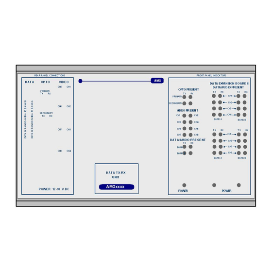
Page 7: Front Panel Indicators
> -40dBm audio present > 0dBm (overload at +6dBm) audio not present or < -40dBm AMG Systems Ltd. reserves the right to make changes to this Page 7 of 12 AMG4707A-DR-SF Instruction Sheet document without notice. The information herein is believed to D18212-01.doc... - Page 8 > 0dBm (overload at +6dBm) audio not present or < -40dBm This represents the audio signals being received from the optical fibre. AMG Systems Ltd. reserves the right to make changes to this Page 8 of 12 AMG4707A-DR-SF Instruction Sheet document without notice.
-
Page 9: Physical Information
Weight ..........1000grams Mounting Details The AMG unit is supplied with a clip-on mounting bracket which should be attached to a panel or wall using 2 off 4.0mm screws, see diagram on page 1 for dimensions. The unit is clipped into the mounting bracket, and is then held firmly in position. - Page 10 This page is intentionally blank. AMG Systems Ltd. reserves the right to make changes to this Page 10 of 12 AMG4707A-DR-SF Instruction Sheet document without notice. The information herein is believed to D18212-01.doc be accurate. No responsibility is assumed by AMG for its use.
- Page 11 This page is intentionally blank. AMG Systems Ltd. reserves the right to make changes to this Page 11 of 12 AMG4707A-DR-SF Instruction Sheet document without notice. The information herein is believed to D18212-01.doc be accurate. No responsibility is assumed by AMG for its use.
- Page 12 This page is intentionally blank. AMG Systems Ltd. reserves the right to make changes to this Page 12 of 12 AMG4707A-DR-SF Instruction Sheet document without notice. The information herein is believed to D18212-01.doc be accurate. No responsibility is assumed by AMG for its use.
Need help?
Do you have a question about the AMG4707A-DR-SF and is the answer not in the manual?
Questions and answers