Table of Contents
Advertisement
Quick Links
Betriebsanleitung
Bitte sorgfältig beachten!
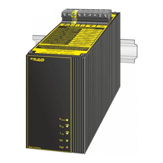
Typ
Einstellbereich der Ausgangsspannung
Range of adjustment output voltage
Ausgangsstrom
output current
Ausgangsleistung
output-power
Wirkungsgrad
efficiency
Vorsicherung (tech. nicht nötig)
Fuse for input (tech. not necessary)
Maße
BxHxT
dimensions
WxHxD
Gewicht
weight
q
Ausgang potentialfrei nach VDE 0551
q
Tropentauglich - Gießharzvollverguss
q
Kurzschlussfest, überlast- und leerlaufsicher
q
Parallelschaltbar - Verpolungsschutz am Ausgang
q
Die rote LED signalisiert eine Störung durch Kurzschluß,
Übertemperatur oder Überlast.
q
Zur besseren Wärmeabfuhr sollten die Geräte einen
Mindestabstand zu anderen Geräten von 15mm halten.
q
Die Geräte eignen sich zur Montage auf 35mm Hutprofil-
schienen oder zum Anschrauben auf Montagefläche.
Für den ordnungsgemäßen Betrieb des
Gerätes ist ein Überspannungsschutz nach
VDE0185-4 / EN62305-4, und ein Netzfilter
vorzusehen.
Aufgrund der internen Transienten-
Schutzschaltung darf die Isolationsprüfung
Ihrer Anlage nicht mit unserem Gerät erfolgen.
Durch den vollständigen Verguss darf das
Gerät nicht geöffnet werden, andernfalls
erlöschen jeglicher Garantie- und
Haftungsanspruch.
Anschlussschema / Cable arrangement
-
U
+
Kontaktbelastung der Relais:
out
- max. Schaltstrom
3,0 Amp.
SNT120
- max. Schaltspannung 30V
/250V
DC
AC
2
Contact-load of the relays:
- max. switched current 3,0Amp.
- max. switched voltage 30V
/250V
1
DC
AC
interne Relais-
!
Belegung
-
internal relay
assignment
PE
85 - 270VAC
oder / or
N
120 - 400VDC
L1
U
Netzspannung
in
line-voltage
Operating instructions
SNT120
Please observe carefully!
SNT12012
SNT12024
SNT12048
10 - 15VDC
23 - 30VDC
48 - 60VDC
20,0A
15,0A
7,5A
240Watt
360Watt
360Watt
91%
93%
93%
bei 115VAC 8,0Amp. träge / bei 230VAC 4,0Amp. träge
at 115VAC 8,0Amp. delayed / at 230VAC 4,0Amp. delayed
83mm x 161mm x 160,5mm
ca. 4,30kg
q
Output separated according to VDE 0551
q
Suitable for the tropics - Epoxy resin casted
q
Short- circuit proof, no-load and overload safe
q
Parallel connection possible -
Protected against pol-permutation at the output
q
The red LED signals a disturbance because of short-circuit,
overload or overtemperature.
q
To be better cooled, the devices should hold a minimum-distance
of 15mm to other appliances.
q
The power supplies are suitable to be fitted on 35mm DIN-rail
or to be screwed on any mounting-surface
For proper operation of the device provide an
overvoltage protection, according VDE0185-4 /
EN62305-4, and a line filter.
Due to the internal transient protection circuit,
the insulation test of your system must not be
carried out with our device.
The device must not be opened as a result of
complete potting, otherwise all warranty and
liability claims will lapse.
Befestigungsarten / Type of fortification
Wandmontage / Wallmounting
DC-Ausgang
DC-output
+
Verbraucher
consumer
Montage auf Hutschiene / Mounting on rail
Für 35mm Hutschienenprofil nach DIN 46277
For rail 35mm acc. to DIN 46277
Öffner Relais-Kontakt 2-1 /
Normally opens relay contact 2-1
Öffnet bei überhöhter Netzteil-Temperatur
oder wenn Ausgangsspannung folgende
Werte unterschreitet
Opens at over temperature or if Output
voltage is below the following values
SNT12012 - U
< 10 V
out
SNT12024 - U
< 21 V
out
Details siehe Rückseite. / Details are shown on backpage
SNT12048 - U
< 44 V
out
Das Relais öffnet 5°C vor erreichen der
kritischen Temperatur.
I
out
The relay opens at 5 ° C before reaching
I
nenn
the critical temperature.
1,5
Powerboost
1,2
1,0
Feineinstellung der
Fine-adjustment
Dauerbetrieb
0,8
Ausgangsspannung
Output voltage
0,6
0,4
Feineinstellung der
ca. 50 - 150%
0,2
Ausgangsstromgrenze
I
Nenn
0
Fine-adjustment of
ca. 50 - 150%
0
10
20
Output current limit
I
Nominal
Allgemeine Sicherheitsvorschriften
Beim Umgang mit Produkten, die mit elektrischen Spannungen in Berührung kommen, müssen
die gültigen VDE / IEC / EN Vorschriften beachtet werden. Besonders sei auf folgende
Vorschriften hingewiesen: VDE 0100, VDE 0550 / 0551, VDE 0711, VDE 0860, IEC 664, IEC
742, IEC 570, IEC 65
Bei Nichtbeachtung der Bedienungsanleitung oder der Anschlussvorschrift, z.B. bei Vertauschen
der Anschlussklemmen, kann das Gerät oder die Anlage beschädigt werden und der Betreiber
verliert seinen möglichen Haftungsanspruch.
Werkzeuge dürfen an Geräten, Bauteilen oder Baugruppen nur benutzt werden, wenn
sichergestellt ist, dass die Geräte von der Versorgungsspannung getrennt sind und interne
elektrische Bauteile entladen sind.
Vor dem Öffnen des Gerätes den Netzstecker ziehen und sicherstellen, dass das Gerät
spannungslos ist und bleibt. Bauteile, Baugruppen oder Geräte dürfen nur in Betrieb genommen
werden, wenn sie vorher in ein berührungssicheres Gehäuse eingebaut wurden. Während des
Einbaus müssen sie stromlos sein.
Spannungsführende Kabel oder Leitungen mit denen das Gerät, das Bauteil oder die Baugruppe
verbunden sind müssen stets auf Isolationsfehler oder Bruchstellen untersucht werden. Bei
Feststellen eines Fehlers in der Zuleitung muss das Gerät unverzüglich aus dem Verkehr
genommen werden, bis die defekte Leitungen ausgewechselt worden sind.
Der Anwender hat dafür Sorge zu tragen, dass die angegebenen Gerätedaten nicht
überschritten werden.
Wenn aus den vorgelegten Beschreibungen für den Anwender oder Erwerber nicht eindeutig
hervorgeht, welche Kennwerte für ein Gerät oder Bauteil gelten, so muss stets ein Fachmann
um Auskunft ersucht werden.
Im Übrigen unterliegt die Einhaltung von Bau- und Sicherheitsvorschriften aller Art ( VDE, TÜV,
Berufsgenossenschaften ) dem Anwender / Käufer.
Verbraucher (z.B. Schütze, Motoren, Magnetventile,
etc.) die nicht ordnungsgemäß nach den relevanten
Richtlinien entstört sind (z.B. Varistoren, RC-Glieder,
etc), können zur Störung bzw. Zerstörung des
Netzgerätes führen.
Technische Daten
Eingangsgrößen
Eingangswechselspannung
Eingangsgleichspannung
Stromaufnahme bei Nennlast
Einschaltstromstoß bei 270VAC
Schutzbeschaltung
Netzausfallüberbrückung
Ausgangsgrößen
Ausgangsspannung U
Nenn
Ausgangstrom I
Nenn
Strombegrenzung
Restwelligkeit (20MHz)
Regelgrößen
Regelabweichung Last
Regelabweichung Netz
Regelzeit
Betriebsdaten
Einschaltdauer (ED)
Arbeitstemperatur
Leistungsabweichung bei Temp.
Lagertemperaturbereich
Kühlung
Schutzeinrichtungen
Für M6 Schrauben
For M6 screws
Vorsicherung
Ausgangssicherung
Überlastschutz
MTBF
Rückseite des Gerätes
Sicherheitsdaten
backside of the unit
Prüfspannung Trafo
Hochspannungsfestigkeit
Funkenentstörgrad
Schutzklasse
Schutzkleinspannung
Umgebungsfeuchte
Schutzart Gehäuse
Schutzart Klemmen
Rückseite des Gerätes
Rüttelfestigkeit
backside of the unit
Angewandte Bauvorschriften
gemäß VDE
Derating
IEC
EN
Boostbetrieb
CSA / UL
Mechanik
Befestigung
30
40
50
60
70
80
90 100
- konform
Temperatur
T / C°
Temperature
General safety rules
When working with products which are in contact to dangerous electrical voltages,
attention must be payed to the relevant valid VDE / IEC / EN regulations. Especialy with
refrence to the following rules:
VDE 0100, VDE 0550 / 0551, VDE 0711, VDE 0860, IEC 664, IEC 742, IEC 570, IEC 65
In case of non-observance of this instructions the unit or other equipment might be
damaged and no warranty or liability could be accepted.
When it is necessary to use tools on the device components parts or subassemblies
make sure that the power is disconnected from the device and all capacities are
discharged.
Before opening the equipment disconnect the power cord and make sure that the
contacts are not energized. It is only allowed to take components parts, subassemblies or
device into operation if they are mounted in an insulated housing. During the installation
all devices have to be disconnected from power sources.
Power cords and leads which are connected to the device, components or subassemblies
have to be inspected for damaged insulation. If a failure is detected the device or the
subassembly has to be put out of service at once. It is not allowed to take the device or
the subassembly into operation before replacing the damaged power cord.
It is up to the user's responsibility that the specification limits of the device are not
exceded.
If the user is not fully able to relate the technical guidelines, a technical adviser has to be
asked for information.
The observance of construction requirements and safety rules (VDE, IEC, employers
liability insurenance i.e.) is subject to the user/customer.
Consumers (e.g. contactors, motors, solenoid valves
etc.) which have not been correctly interference-
suppressed in accordance to the relevant guidelines
(e.g. varistors, RC elements, etc.) may cause power
supply regulation to malfunction.
Input data
85 - 270Volt
44 - 66Hz
Input voltage AC
120Volt - 400Volt
Inputvoltage DC
bei 115VAC max. 4,0A / bei 230VAC max. 2,0A
Input current at nominal load
<8,2A
Input current peak at 270VAC
Transientenüberspannungsschutz Varistor
Protective circuit
20 mSek. typ.
Hold-up time
Output data
siehe Tabelle links
Output voltage U
siehe Tabelle links
Output current I
Nominal
einstellbar 0,5.....1,5 x I
Current limiting
N
< 50mVrms
Residual ripple (20MHz)
Control data
< 200mV bei Laständerung 10...90%
Control deviation load
< 10mV bei Netzspannungsänderung ±10%
Control deviation supply
< 10 mSek. bei Laständerung 10...90%
Control time
Operating data
100%
Duty circle
- 40°C bis 80°C
Operating temperature range
ab 50°C
Derating
- 40°C...105°C
Storage temperature range
natürliche Konvektion
Cooling
empfohlener Freiraum je 15mm
Safety devices
siehe Tabelle links
Fuse for input
nicht erforderlich da kurzschlussfest
Fuse for output
im Gerät integriert
Overload protection
>380.000 h
MTBF
Safety data
5 kVac gemäß VDE 0551
Test voltage transformer
Eingang / Ausgang 4,4 kVac
High voltage resistance
nach VDE 0806 / IEC 380
gemäß VDE 0871 B, EN 55022/B
Degree of EMI suppresion
Klasse 1, mit PE Anschluss (EN 60950)
Protection class
PELV (EN60204), SELV (EN 60950)
Extra low safety potential
95% relative Feuchte im Jahresdurchschnitt
Ambient humidity
Betauung möglich - tropentauglich
IP 68
Protective class enclosure
IP 20 (BGV A3)
Protective class terminals
>30g bei 33Hz in X,Y und Z,
Vibration proof
nach IEC 60068-2-27
Applied construction regulations
VDE 0100, 0110, 0113, 0551, 0160/W2, 0806
according to VDE
IEC 60950,IEC61000-6-1-2-3-4,IEC60068-2-3
IEC
IEC 60068-2-11-52,IEC 60529,IEC 380
EN60950-1,EN50081-1,EN50081-2,EN50082-1
EN
EN61000-6-1-2-3-4,EN50178,EN55022
EN55011,EN61000-3-2,EN61000-3-3,EN50204
EN60204,EN60529,EN61000-4-2-3-4-5-6-8-11
EN60068-1,EN60068-2-1-2-3-6-27-30
EN45501,EN50021,EN61558-2-17
CSA-C 22.2 / UL60950, UL508, UL1950
CSA / UL
Mechanics
Mounting
Auf Hutschiene nach DIN46277 und aufschraubbar
®
©2012
GmbH
Technical data
85 - 270Volt
44 - 66Hz
120Volt - 400Volt
at 115VAC max. 4.0A / at 230VAC max. 2.0A
<8.2A
Transient voltage suppressor Varistor
20 mSek. typ.
see table left
Nominal
see table left
adjustable 0.5.....1.5 x I
N
< 50 mVrms
< 200mV with load variation 10...90%
< 10mV with supply variation ±10%
< 10 mSek. with load variation 10...90%
100%
- 40°C to 80°C
from 50°C
- 40°C...105°C
selfcooling
recommended respective distance 15mm each
see table left
not necessary - cont. short-circuit proof
integrated into device
>380,000 h
5 kVac in accordance to VDE 0551
Primary circuit - secondary circuit 4,4 kVac
acc. to VDE 0806 / IEC 380
in acc. to VDE 0871 B, EN 55022/B
Class 1, with PE connection (EN 60950)
PELV (EN60204), SELV (EN 60950)
95% relative humidity, yearly average dewing
allowed for use in tropical ambient
IP 68
IP 20 (BGV A3)
>30g at 33Hz in X,Y and Z,
acc. to IEC 60068-2-27
VDE 0100, 0110, 0113, 0551, 0160/W2, 0806
IEC 60950,IEC61000-6-1-2-3-4,IEC60068-2-3
IEC 60068-2-11-52,IEC 60529,IEC 380
EN60950-1,EN50081-1,EN50081-2,EN50082-1
EN61000-6-1-2-3-4,EN50178,EN55022
EN55011,EN61000-3-2,EN61000-3-3,EN50204
EN60204,EN60529,EN61000-4-2-3-4-5-6-8-11
EN60068-1,EN60068-2-1-2-3-6-27-30
EN45501,EN50021,EN61558-2-17
CSA-C 22.2 / UL60950, UL508, UL1950
on rails acc. to DIN 46277 and with screws
Stand: 15.05.2012
Postfach 1521
Telefon: 04102 - 42082
D - 22905 AHRENSBURG
Telefax: 04102 - 40930
www.feas.de
Advertisement
Table of Contents

Related Manuals for FEAS SNT120


Summary of Contents for FEAS SNT120
- Page 1 Allgemeine Sicherheitsvorschriften General safety rules Operating instructions Betriebsanleitung SNT120 Beim Umgang mit Produkten, die mit elektrischen Spannungen in Berührung kommen, müssen When working with products which are in contact to dangerous electrical voltages, Bitte sorgfältig beachten! Please observe carefully! die gültigen VDE / IEC / EN Vorschriften beachtet werden. Besonders sei auf folgende attention must be payed to the relevant valid VDE / IEC / EN regulations.
- Page 2 6 mm 163 mm 19 mm 87,5 mm 71,5 mm In Abhängigkeit zur Umgebungstemperaur 52,5 mm 52,5 mm 15 mm 15 mm und Lastentnahme sollte gegebenenfalls Fremd- belüftung eingesetzt werden. 135 mm Depending on the ambient temperature and drawn load, external ventilation should be used.
- Page 3 >1300V >600V <600V Blitz- und Transientenschutz lightning and overvoltage protection Netzfilter linefilter EMV Schutz e.g. EMC protection FEAS NFK device e.g. SNT230 Stand: 01.02.2012 ® ©2012 Postfach 1521 Telefon: 04102 - 42082 - konform D - 22905 AHRENSBURG Telefax: 04102 - 40930 GmbH www.feas.de...
Need help?
Do you have a question about the SNT120 and is the answer not in the manual?
Questions and answers