Table of Contents
Advertisement
Quick Links
Betriebsanleitung
Bitte sorgfältig beachten!
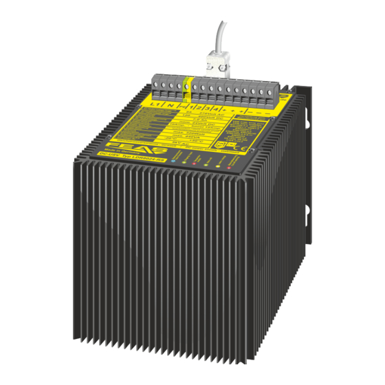
Für die Modelle:
- LDR8024-RS -
Eingangsspannung - Input voltage
Kapazität - Capacity
-
Ausgangsspannung
Outputvoltage
folgt der Akkuspannung (U
)
follows the accu voltage (U
Puffer
Ausgangsstrom - Output current
Pufferzeit - Hold-up-time
Die „Ergänzende Anleitung zum
Betrieb des LDR8024-RS über die
!
RS-Schnittstelle" finden Sie im
Downloadbereich des LDR8024-RS
unter feas.de).
Stand / as at: 17.11.2021
Postfach 1521
D - 22905 Ahrensburg
© 2021
Operating instructions
Please observe carefully!
Complementing the:
85V ...270V / 120V ....400V
AC
AC
DC
7Ah
20,0 - 27,6 VDC
)
buffer
10A (Boost max.14A)
max. 10A/24V
40min
The "Supplementary instructions
for operating the LDR8024-RS via
!
the RS interface" can be found in
the download area of the LDR8024-
RS at feas.de).
Telefon: +49 4102 42082
E-Mail: verkauf@feas.de
Fax: +49 4102 40930
Internet: www.feas.de
Bitte sorgfältig beachten!
1. Allgemeine Sicherheitsvorschriften
Beim Umgang mit Produkten, die mit elektrischen Spannungen in
Berührung kommen, müssen die gültigen VDE / IEC / EN Vorschriften
beachtet werden. Besonders sei auf folgende Vorschriften hingewiesen:
VDE 0100, VDE 0550 / 0551, VDE 0711, VDE 0860, IEC 664, IEC 742,
IEC 570, IEC 65
DC
Bei Nichtbeachtung der Bedienungsanleitung oder der
Anschlussvorschrift, z.B. bei Vertauschen der Anschlussklemmen, kann
das Gerät oder die Anlage beschädigt werden und der Betreiber verliert
seinen möglichen Haftungsanspruch.
Werkzeuge dürfen an Geräten, Bauteilen oder Baugruppen nur benutzt
werden, wenn sichergestellt ist, dass die Geräte von der
Versorgungsspannung getrennt sind und interne elektrische Bauteile
entladen bzw Akkus ausgebaut sind.
Vor dem Öffnen des Gerätes den Netzstecker ziehen und sicherstellen,
dass das Gerät spannungslos ist und bleibt. Bauteile, Baugruppen oder
Geräte dürfen nur in Betrieb genommen werden, wenn sie vorher in ein
berührungssicheres Gehäuse eingebaut wurden. Während des Einbaus
müssen sie stromlos sein.
Spannungsführende Kabel oder Leitungen mit denen das Gerät, das
Bauteil oder die Baugruppe verbunden sind müssen stets auf
Isolationsfehler oder Bruchstellen untersucht werden. Bei Feststellen
eines Fehlers in der Zuleitung muß das Gerät unverzüglich aus dem
Verkehr genommen werden, bis die defekten Leitungen ausgewechselt
worden sind.
Der Anwender hat dafür Sorge zu tragen, dass die angegebenen
Gerätedaten nicht überschritten werden.
Wenn aus den vorgelegten Beschreibungen für den Anwender oder
Erwerber nicht eindeutig hervorgeht, welche Kennwerte für ein Gerät
oder Bauteil gelten, so muss stets ein Fachmann um Auskunft ersucht
werden.
Im übrigen unterliegt die Einhaltung von Bau- und Sicherheitsvorschriften
aller Art (VDE, TÜV, Berufsgenossenschaften ) dem Anwender / Käufer.
Die RS-232-Schnittstelle ist (anders als RS-485)
nicht von der DC-Seite potentialgetrennt.
Bei Anschluss z.B. an Rechner muss gegebenenfalls für
Potentialtrennung gesorgt werden!
Verbraucher (z.B. Schütze, Motoren, Magnetventile, etc.) die
nicht ordnungsgemäß nach den relevanten Richtlinien
entstört sind (z.B. Varistoren, RC-Glieder, etc), können zur
Störung bzw. Zerstörung des Netzgerätes führen.
Für den ordnungsgemäßen Betrieb des Gerätes ist ein
Überspannungsschutz nach VDE0185-4 / EN62305-4,
eine Vorsicherung, gemäß Tabelle, und optional ein
Netzfilter vorzusehen.
Grobschutz
Mittelschutz
Surge protective
Surge protective
devices
Typ1
>1300V
- konform
Blitz- und Transientenschutz
lightning and overvoltage protection
Aufgrund der internen Transienten-Schutzschaltung
sollte die Isolationsprüfung Ihrer Anlage nicht mit
unserem Gerät erfolgen.
Please observe carefully!
1.General safety instructions
When working with products which are in contact to dangerous electrical
voltages, attention must be payed to the relevant valid VDE / IEC / EN
regulations. Especially with reference to the following regulations:
VDE 0100, VDE 0550 / 0551, VDE 0711, VDE 0860, IEC 664, IEC 742,
IEC 570, IEC 65
In case of non-observance of this instructions the unit or other equipment
might be damaged and no warranty or liability could be accepted.
When it is necessary to use tools on the device component parts or
subassemblies make sure that the power is disconnected from the device
and all capacities are discharged.
Before opening the device disconnect the power cord and make sure that
the contacts are not energized. It is only allowed to take component
parts, subassemblies or devices into operation if they are mounted in an
insulated housing. During installation all devices have to be disconnected
from power sources.
Power cords and leads which are connected to the device, components
or subassemblies have to be inspected for damaged insulation. If a
failure is detected the device or the subassembly has to be put out of
service at once. It is not allowed to take the device or the subassembly
into operation before replacing the damaged power cord.
It is up to the user's responsibility that the specification limits of the
device are not exceeded.
If the user is not fully able to relate the technical guidelines, a technical
adviser has to be asked for information.
The observance of construction requirements and safety regulations
(VDE, IEC, employers liability insurenance i.e.) is subject to the
user/customer.
RS232 interface (unlike the RS485 interface) is
not electrically isolated from the DC side.
When connecting e.g. to a computer potential separation
must be ensured!
Consumers (e.g. contactors, motors, solenoid valves etc.)
which have not been correctly interference-suppressed in
accordance to the relevant guidelines (e.g. varistors, RC
elements, etc.) may cause power supply regulation to
malfunction.
For proper operation of the device provide an
overvoltage protection, according VDE0185-4 /
EN62305-4, an input fuse as shown in table and
optionally a line filter.
Überspannungs- und Transientenschutz
Overvoltage and Transientprotection
VDE0185-4 / EN62305-4
Feinschutz
Surge protective
devices
devices
Typ2
Typ3
>600V
<600V
EMV Schutz
EMC protection
Due to the internal transient protection circuit, the insulation
!
test of your system should not be carried out with our device.
Netzfilter
device
linefilter
e.g. SNT230
e.g.
FEAS NFK
Advertisement
Table of Contents

Subscribe to Our Youtube Channel
Related Manuals for FEAS LDR8024-RS


Summary of Contents for FEAS LDR8024-RS
- Page 1 Die „Ergänzende Anleitung zum The "Supplementary instructions failure is detected the device or the subassembly has to be put out of Betrieb des LDR8024-RS über die for operating the LDR8024-RS via Spannungsführende Kabel oder Leitungen mit denen das Gerät, das service at once.
- Page 2 Das LDR kann direkt an die Wand oder ein Montageblech The LDR can be mounted at the wall or any mounting sheet. Take (see download area of the LDR8024-RS at feas.com). zum Betrieb des LDR8024 über die RS-Schnittstelle“ geschraubt werden. Beachten Sie dazu die Hinweise.
- Page 3 9. Wartung 9. Mainenance 9. Maintenance 9. Wartung 8. LED Anzeigen - LED Display LDR80-RS Zur Vermeidung eines Unfalls müssen im Falle der To avoid an accident in case of maintenance or Wartung oder Fehlerbehebung (z.B. Kurzschluss auf der troubleshooting (for example short circuit on the Sekundärseite) die Versorgungszuleitungen auf der secondary side) the electrical supply on the primary / Primär-/ Sekundärseite von den Klemmen getrennt...
- Page 4 Capacity in % -10°C 21,0 of the rated capacity 20,0 -20°C at different Postfach 1521 Telefon: +49 4102 42082 E-Mail: verkauf@feas.de 3,5 A 1,5 A 0,9 A 19,0 temperatures D - 22905 Ahrensburg Fax: +49 4102 40930 Internet: www.feas.de 0 30 60...
Need help?
Do you have a question about the LDR8024-RS and is the answer not in the manual?
Questions and answers