Advertisement
Quick Links
Betriebsanleitung
Bitte sorgfältig beachten!
Für die Modelle:
SNT13012-K, SNT13024-K, SNT13048-K
®
Postfach 1521
GmbH
D - 22905 AHRENSBURG
©2022
Operating
SNT130-K
instructions
Please observe carefully!
148, 0
Telefon: 04102 - 42082
Telefax: 04102 - 40930
1. Funktionsweise
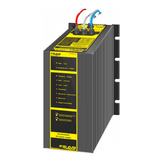
Das SNT130-K ist ein Schaltnetzteil zur Speisung von
Verbrauchern aus dem Niederspannungsnetz. Die Kühlung
erfolgt über Luftkonvektion am Gehäuse-Kühlprofil. Bitte die
"Derating-Kurve" beachten.
2. Montage
Das SNT130-K kann mit acht M8-Schrauben an eine Wand
geschraubt werden. Hierzu bitte die Bohrmaße auf der letzten
Seite beachten. ACHTUNG! Zur besseren Wärmeabfuhr sollte
das Gerät einen Freiraum von 15mm haben.
3. Elektrischer Anschluss
Das Gerät laut Anschluss-Schema unten anschließen. Hierbei
unbedingt die allgemeinen Sicherheitsvorschriften beachten.
Unsachgemäßer Anschluss kann zu einem Defekt des Gerätes
führen.
!
Kontaktbelastung der Relais:
- max. Schaltstrom
3,0 Amp.
- max. Schaltspannung 30V
Contact-load of the relays:
- max. switched current 3.0Amp.
- max. switched voltage 30V
Feineinstellung der
Ausgangsspannung
Fine-adjustment of
Output voltage
Feineinstellung der
Ausgangsstrom-
begrenzung
Fine-adjustment of
Output current
limitation
Normalbetrieb - Standard function
interne Relais-
Belegung
internal relays
assignment
- konform
Feineinstellung der Ausgangsspannung
to apply for:
Diese sollte nicht im Fuse-Mode
erfolgen!
Fine-adjustment of Output voltage
This should not be made in Fuse
Mode
Feineinstellung der Ausgangs-
Strombegrenzung
Fine-adjustment of Output current
www.feas.de
limitation
Stand: 24.10.2022
1. Mode of operation
The SNT130-K is a power supply to supply consumers from
low voltage network.The cooling of the device takes place via
air convection at the case heatsink. Please observe the
derating
2. Installation
The SNT130-K can be mounted on a wall with eight M8-
screws. Take notice of the drilling dimensions on the last page.
CAUTION! For improved heat dissipation, the device
should have a minimum free space of 15 mm.
3. Electrical connection
Take care of a correct electrical connection. Take the wiring
diagram at the bottom of this side as help. Inappropriate
connection can lead to a defect of the device.
Anschlussschema / Wiring diagram
U
out
Bei Stromentnahme von mehr
als 25A muss der Strom
gleichmäßig über alle
Ausgangsklemmen verteilt
werden.
!
If the output current exceeds
25A, the output current has
to be uniformly distributed
over the whole output
terminals.
3
2
1
SNT130-K
- Verbraucher
+
consumer
-
+
Nur Akkus oder
wiederaufladbare Batterien laden!
!
Only charge accumulators or
rechargeable batteries!
Auf Ladeschlussspannung der Batterie einstellen!
!
Adjust to maximum peak voltage of battery!
Derating
I
out
I
nenn
Boostbetrieb
1,2
boost mode
Powerboost
1,0
Dauerbetrieb
0,8
continuous duty
0,6
0,4
0,2
0
0
10
20
30
40
50
60
70
80
90 100
Temperatur / temperature
T / C°
Schlafmodus - Standby
3
2
1
SNT130-K
Reset
Das Gerät wird durch Setzen einer
Brücke zwischen Pin 4 und 5 in den
Schlafmodus versetzt. Es befindet
sich im Bereitschafsmodus, ist aber
von der Last getrennt.
The device is switched to sleep mode
by setting a bridge between pins 4
and 5. It is in standby mode but
disconnected from the load.
Advertisement

Subscribe to Our Youtube Channel
Related Manuals for FEAS SNT130-K


Summary of Contents for FEAS SNT130-K
- Page 1 2. Installation 2. Montage The SNT130-K can be mounted on a wall with eight M8- Das SNT130-K kann mit acht M8-Schrauben an eine Wand screws. Take notice of the drilling dimensions on the last page. geschraubt werden. Hierzu bitte die Bohrmaße auf der letzten CAUTION! For improved heat dissipation, the device Seite beachten.
- Page 2 External voltage External voltage simultaneously the output at output OK at output not OK voltage decreases, so the Schlafmodus / Standby message "Output" can also be SNT130-K Netz - Ausgang - Ausgang - Last - Überstrom - enabled. Temp green...
- Page 3 Das Überwachungsmanagement des SNT130-K erlaubt eine Vielzahl an Einstellmöglichkeiten am Gerät und kann über zwei The monitoring management of the SNT130-K allows a variety of settings on the device. It can be remotely monitored via two integrierte Relais-Kontakte fernüberwacht werden.
- Page 4 Übertemperatur erreicht - Over-Temperature is reached Das SNT130-K kann über den 7-poligen Stecker (Pins The SNT130-K can be used in two different modes by 4 und 6) in zwei Betriebsarten benutzt werden. using the 7-pin plug (Pins 4 and 6) and the Sollte die Gerätetemperatur auf über 85°C steigen,...
- Page 5 VDE / IEC / EN Abschnitt 6) kann die Ausgangsspannung des the output voltage of the SNT130-K can be adjusted. beachtet werden. Besonders sei auf folgende Vorschriften hingewiesen: regulations. Especialy with refrence to the following rules: SNT130-K eingestellt werden.
-
Page 6: Technische Daten
10. Technische Daten 10. Technical Data Maße Rückseite - Dimensions backside Eingangsgrößen Input data Eingangswechselspannung 85 - 270V (44 - 66Hz) AC input voltage 85 - 270V (44 - 66Hz) Eingangsgleichspannung 120 - 400V DC input voltage 120 - 400V Stromaufnahme bei Nennlast bei 115V max.
Need help?
Do you have a question about the SNT130-K and is the answer not in the manual?
Questions and answers