Advertisement
QUICK START GUIDE FOR DEMONSTRATION CIRCUIT 660
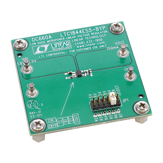
DESCRIPTION
Demonstration circuit DC660 is a low noise micro-
power voltage regulator using the LTC1844 ultra-low
dropout CMOS linear regulator, which comes in a tiny
5-Pin SOT-23 package. The DC660 has an input volt-
age range from 1.8V to 6.5V, and is capable of deliv-
ering 150 mA max. The DC660 is able to use ceramic
capacitors, due to the LTC1844 capability of maintain-
ing stability with ultra-low ESR capacitors. With the
QUICK START PROCEDURE
DC660 is easy to set up for evaluating the perform-
ance of the LTC1844.
equipment configuration, set up the circuit accord-
ing to the diagram in Figure 1.
Please follow the procedure outlined below for
proper operation.
1.
Before proceeding to test, insert jumper JP1
into the 1.5V option and apply no load
across Vout.
2.
Apply 1.6V across Vin (to Gnd).
10mA of load current.
should be 1.5V +/- 2% (1.47V to 1.53V).
3.
Vary the input voltage from 1.6V to 6.5V
and the load current from 10 mA to 100 mA.
Vout should measure 1.5V +/- 4% (1.44V to
1.56V).
4.
Turn off the input power and move jumper
JP1 into any of the remaining output voltage
options: 1.8V, 2.5V, 2.8V, or 3.3V. Re-apply
Arrow.com.
Downloaded from
LOW NOISE MICROPOWER LINEAR VOLTAGE REGULATOR
For proper measurement
Draw
Measure Vout; it
small size ceramic capacitors, tiny SOT-23 package of
the LTC1844, plus its low quiescent current –
maximum 80uA over temperature, the DC660 voltage
regulator is ideally suited for hand-held applications,
such as cellular phones or PDAs.
Gerber files for this circuit are available. Call the
LTC Factory.
power, and, just as in the 1.5V test, the out-
put voltage should read Vout +/- 2% toler-
ance under static line and load conditions,
and +/- 4% tolerance under dynamic line
and load conditions.
5.
When finished evaluating, turn off the input
power.
Warning - If long leads are used to power the demo
circuit, the input voltage at the part could "ring".
This ringing could affect the operation of the circuit
or even exceed the maximum voltage rating of the
IC. To eliminate this, insert a small tantalum ca-
pacitor
(for
instance,
TAJW226M010R) on the pads between the input
power and return terminals on the bottom of the
demo board. The (greater) ESR of the tantalum will
dampen the (possible) ringing voltage due to the
use of long input leads. On a normal, typical PCB,
with short traces, the capacitor is not needed.
LTC1844
an
AVX
part
#
1
Advertisement
Table of Contents

Related Manuals for Linear Technology DC660


Summary of Contents for Linear Technology DC660
- Page 1 1.8V to 6.5V, and is capable of deliv- such as cellular phones or PDAs. ering 150 mA max. The DC660 is able to use ceramic Gerber files for this circuit are available. Call the capacitors, due to the LTC1844 capability of maintain- LTC Factory.
- Page 2 QUICK START GUIDE FOR DEMONSTRATION CIRCUIT 660 LOW NOISE MICROPOWER LINEAR VOLTAGE REGULATOR Figure 1. Proper Measurement Equipment Setup Figure 2. Measuring Input or Output Ripple Arrow.com. Arrow.com. Downloaded from Downloaded from...
- Page 3 QUICK START GUIDE FOR DEMONSTRATION CIRCUIT 660 LOW NOISE MICROPOWER LINEAR VOLTAGE REGULATOR Arrow.com. Arrow.com. Arrow.com. Downloaded from Downloaded from Downloaded from...
Need help?
Do you have a question about the DC660 and is the answer not in the manual?
Questions and answers