
Related Manuals for YOKOGAWA GD402G /M1


Summary of Contents for YOKOGAWA GD402G /M1
- Page 1 User’s Manual Model GD402G /M1 Gas Density Meter (Converter with Terminal Block) IM 11T03E01-51E IM 11T03E01-51E 6th Edition (YK)
-
Page 2: Introduction
The GD402 operates with the same parameters set when it was delivered (default data) , when it is put into operation under these conditions. Media No. IM 11T03E01-51E 6th Edition : June 2021 (YK) IM 11T03E01-51E All Rights Reserved Copyright © 2007, Yokogawa Electric Corporation... - Page 3 Equipments The GD402G should only be used with equipment that meets the relevant IEC standard. Yokogawa accepts no responsibility for the misuse of this unit. CAUTION Modification and adaptation of the instrument’s parts, wiring and construction are prohibited. WARNING l Power Supply Ensure the power supply voltage matches instrument before turning ON the power.
- Page 4 • If any protection or safety circuit is required for the system controlled by the product or for the product itself, prepare it separately. • Be sure to use the spare parts approved by Yokogawa Electric Corporation (hereafter simply referred to as YOKOGAWA) when replacing parts or consumables.
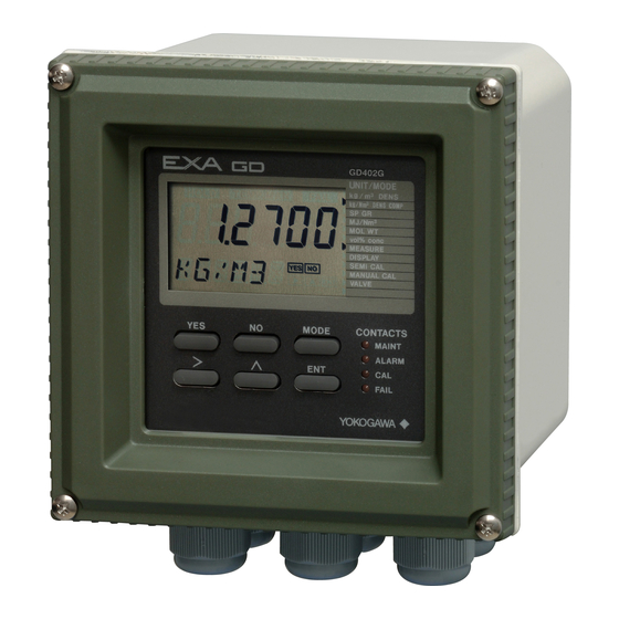
- Page 5 <Introduction> Information Indicated on Product Indicated with angle brackets < > as: <n> (lit) or <o> (unlit), meaning the contact output indicator lamp along with its state <MEASURE> mode, meaning the mode of measurement Information on the State of Blinking Indicated in shaded typography as: (blinking) , in contrast to (lit)
-
Page 6: Ce Marking Products
Product Disposal The instrument should be disposed of in accordance with local and national legislation/ regulations. Authorized Representative in EEA The Authorized Representative for this product in EEA is Yokogawa Europe B.V. (Euroweg 2, 3825 HD Amersfoort, The Netherlands). IM 11T03E01-51E... -
Page 7: After-Sales Warranty
In the following cases, customer will be charged repair fee regardless of warranty period. • Failure of components which are out of scope of warranty stated in instruction manual. • Failure caused by usage of software, hardware or auxiliary equipment, which Yokogawa Electric did not supply. • Failure due to improper or insufficient maintenance by user. -
Page 8: Table Of Contents
Toc-1 <CONTENTS> Model GD402G /M1 Gas Density Meter (Converter with Terminal Block) IM 11T03E01-51E 6th Edition CONTENTS Introduction ......................i CE marking products ..................v After-sales Warranty ...................vi SPECIFICATIONS ..................1-1 1.1 Specifications ....................1-1 1.1.1 General Specifications ............... 1-1 1.1.2 GD40G, T, V, R Detector ..............1-3 1.1.3... - Page 9 Toc-2 <CONTENTS> 2.4.5 Cable Wired to GD40 Detector ............. 2-14 2.4.6 Wiring to Model EJX310A pressure transmitter ....... 2-14 2.4.7 Cables Wired to the Ground ............2-15 OPERATION ....................3-1 Preparation for Operation ................3-1 3.1.1 Inspecting Installation, Piping and Wiring Workmanship ....3-1 3.1.2 Supplying Power ................
- Page 10 Toc-3 <CONTENTS> 6.2.1 Parameter Setting at Operation Level ..........6-7 6.2.2 Parameter Setting at Setting Level ..........6-12 6.2.3 Parameter Setting at Service Level ..........6-16 HYDROGEN PURITY/PARAMETER SETTING ........7-1 Setting Parameters ................... 7-2 7.1.1 Setting Parameters at Measurement Level ........7-2 7.1.2 Setting Parameters at Operation Level ..........
- Page 11 Toc-4 <CONTENTS> 11.1.4 Replacing the Fuse ................11-2 11.1.5 Cleaning ................... 11-2 11.2 Inspection In Case of Failure ................. 11-3 11.2.1 Inspecting the Analyzer in an Alarm Status ........11-3 11.2.2 Inspecting the Analyzer in a FAIL Status ......... 11-4 Customer Maintenance Parts List ...........CMPL 11T3E1-01E Customer Maintenance Parts List ...........CMPL 11T3E1-02E Revision Information ....................i...
-
Page 12: Specifications
<1. Specifications> SPECIFICATIONS 1.1 Specifications The specifications of the GD402 gas density meter as described below. Certificate is approved for model GD402G, GD40G. 1.1.1 General Specifications System Components (1) GD40G, T, V, R Detector: Rainproof for outdoor use (equivalent to IP65/NEMA4X) (see note under “1.1.2 Ambient conditions” on page 1-5.) Ambient Temperature : -10 to 60°C Ambient Humidity : 5 to 95%RH GD40G : General purpose detector. (Non-Explosion-proof) Electrical connection : 1/2 NPT female Process connection : 1/4 NPT female GD40T : FM Explosion-proof and Intrinsically safe Approval. - Page 13 <1. Specifications> Ambient Temperature : -10 to 55°C Ambient Humidity : 5 to 95%RH General purpose converter. (Non-Explosion-proof). Electrical connection: 21mm (0.9inch) in diameter. Pg 13.5 cable glands included (3) EJX310A Absolute pressure transmitter (optional) See GS 01C25D01-01EN for EJX310A. Sample Gas conditions Sample gas: All gases except for corrosive gas and acetylene gas. Temperature: -10 to 60°C (non-condensing) Pressure: Max.
-
Page 14: Gd40G, T, V, R Detector
<1. Specifications> CAUTION This instrument is a Class A product, and it is designed for use in the industrial environment. Please use this instrument in the industrial environment only. Characteristics GD402 specification list Item Density kg/m Density lb/ft Specific Gravity Molecular Weight Concentration vol% 0 - 6 (compensated) 0 - 0.4 (compensated) Range... -
Page 15: Gd402G Converter
<1. Specifications> Weight Approximately 7 kg (with pipe mounting bracket) Detector unit When the system is ordered to be used as a hydrogen purity meter, an optional pressure transmitter is required for pressure compensation. • If /EJAJ1, /EJAF2, /EJAF3 or, /EJAF4 are ordered, the detector unit and the pressure transmitter and the tubing in between will all be integrated on a single mounting plate. -
Page 16: Model And Suffix Codes
<1. Specifications> 1.2 Model and Suffix Codes 1.2.1 Gas Density Converter [Style: S2] Model Suffix code Option code Description GD402G - - - - - - - - - - - - - - - - - - General purpose model, 6 cable glands included. Power - - - - - - - - - 24 V DC supply... -
Page 17: Two-Core, Double-Shielded Cable
<1. Specifications> GD40 Standard Accessory Item Part Number U-Bolt Assy *1 D0117XL-A Bracket *1 K9214HD Bracket *1 K9214HE Gland *2 G9601AM Not supplied when option code “/EJAJ1 ”, “/EJAF2 ”, “/EJAF3 ” or “/EJAF4 ” is specified. Supplied only for GD40R. 1.2.3 Two-core, Double-Shielded Cable Normally two conductor shielded cable can be used, but when failure arises from noises... -
Page 18: External Views And Dimension
<1. Specifications> 1.3 External Views and Dimension 1.3.1 GD402G Converter (General purpose) GD402G-□-E-E/M1 /PA (Converter with Terminal Block, Panel mounting) Unit : mm M3x8 (Terminal Screws) Panel Mounting M6x10 (4 Screw Bolts) Panel Mounting Option code: /PA Cable Inlet Max. 12 (Panel Thickness) 110.5 Dimension of Panel Cutout Grounding Terminal M4 Screws F0103.ai IM 11T03E01-51E... -
Page 19: Gd40 Detector
<1. Specifications> 1.3.2 GD40 Detector Model GD40- /EJAJ1, /EJAF2, /EJAF3, /EJAF4 approx. 443 (17.5) Unit: mm (in.) Detector Pressure transmitter EJX wiring port See Table GD40 Detector wiring port See Table Cable gland is included only in /EJAJ1(T) Gas in (2.8) 100 (3.9) 150 (5.9) See Table... -
Page 20: Detector Unit (Intrinsically Safe, Explosion-Proof)
<1. Specifications> 1.3.3 Detector Unit (Intrinsically Safe, Explosion-proof) l Bracket for Pipe Mounting : GD40 Unit: mm (in.) Approx. 191 (7.5) Approx. 264 (10.4) Approx. 92 (3.6) Approx. 193 (7.6) Grounding terminal (3 mm (0.11) screw) Wiring hole, GD40R: G1/2 Pipe-mounting GD40V: 1/2NPT hardware GD40T: 1/2NPT Sample gas inlet GD40G: 1/2NPT GD40R: Rc1/4 GD40V: 1/4NPT GD40T: 1/4NPT... - Page 21 Blank Page...
-
Page 22: Installation, Wiring And Piping
<2. Installation, Wiring and Piping> INSTALLATION, WIRING AND PIPING The GD402 Gas Density Meter is thoroughly inspected at the factory and carefully packed to ensure the equipment does not suffer any damage during transportation. The package should also be handled with care when unpacking to prevent the equipment from undergoing severe mechanical shock. -
Page 23: Gd40T (Fm Explosion-Proof And Intrinsically Safe Approval)
• Take care not to generate mechanical spark when access to the instrument and peripheral devices in hazardous locations. 4. Maintenance and Repair • T he instrument modification or parts replacement by other than authorized representative of Yokogawa Electric Corporation is prohibited and will void the approval of Factory Mutual Research Corporation. IM 11T03E01-51E... -
Page 24: Gd40V (Csa Explosion-Proof And Intrinsically Safe Approval)
• Open circuit before removing cover. • Substitution of components may impair intrinsic safety. • Take care not to generate mechanical spark when access to the instrument and peripheral devices in hazardous locations. 4. Maintenance and Repair • T he instrument modification or parts replacement by other than authorized representative of Yokogawa Electric Corporation is prohibited and will void the certification of CSA International. IM 11T03E01-51E... -
Page 25: Mounting The Detector
<2. Installation, Wiring and Piping> 2.1.4 Mounting the Detector The detector is designed for pipe mounting. Unit: mm (in.) Approx. 191 (7.5) Approx. 264 (10.4) Approx. 92 (3.6) Approx. 193 (7.6) Grounding terminal (3 mm (0.11) screw) Wiring hole, GD40R: G1/2 Pipe-mounting GD40V: 1/2NPT hardware... -
Page 26: Installing The Converter
<2. Installation, Wiring and Piping> Installing the Converter 2.2.1 Selecting the Location Ease of operation Select a location where you can easily view the readings on the display and work with the keys. Installing the converter closer to the detector will ease your maintenance work, including calibration. -
Page 27: Mounting The Converter
<2. Installation, Wiring and Piping> 2.2.2 Mounting the Converter Panel Mounting Unit: mm Dimension of Panel Cutout Panel Converter Bracket Insert the converter in the panel cutout before attaching the brackets. Fixing screws (2 pcs) F0209.ai Figure 2.8 Panel Mounting Piping CAUTION In the case of replacement range, H... - Page 28 EJX (Explosion-proof pressure transmitter) Gas for zero calibration Detector unit (EJX and GD40 detector mounted on plate) (Supplied by Yokogawa) Gas for span calibration Pressure regulator for gas cylinder Supplied by customer. *1: P1 (Inlet pressure) < = Max. 0.5 MPa (71 psi) *2: P1 (Inlet pressure) - P2 (Outlet pressure) >...
-
Page 29: Wiring
<2. Installation, Wiring and Piping> Wiring WARNING Danger High Voltage ! Some parts of the meter’s internal assembly have high voltages. Inadvertent contact with those parts may result in electrical shock or injury. ALWAYS turn off the power to the meter before removing the rear or front cover by using external circuit breaker. This section explains how to wire the GD402 Analyzers. Note that this document is limited to the basic system configuration only (detector, converter and pressure transmitter). - Page 30 <2. Installation, Wiring and Piping> GD402G /M1 Converter MAINTENANCE CONT MAINT Contact input Contact output OUT1 Isolated 4-20 mA Output ALARM with BRAIN Communication Contact output OUT2 FAIL Isolated 4-20 mA Output FAIL Contact output Pressure Transmitter FUNCTION FUNC Contact output...
- Page 31 2-10 <2. Installation, Wiring and Piping> Electrical Noise Protection If a malfunction due to noise occurs, strengthen measures against noise. For example, ground the detector body or use a double-shielded cable. If a double-shielded cable is used, ground shields of each conductor at one end. Ground one end of the outer shield on the detector side to the detector case and connect the other end on the converter side to terminal 13.
-
Page 32: Cables Wired To Power Supply
2-11 <2. Installation, Wiring and Piping> 2.4.2 Cables Wired to Power Supply The GD402G bears the CE marking. When using the meter in a place where the CE marking is obligatory, or when performance meeting the CE marking requirements is needed, the following wiring is required. -
Page 33: Cables Wired To Outputs
2-12 <2. Installation, Wiring and Piping> 2.4.3 Cables Wired to Outputs These cables are used to transmit 4-20 mA DC signals and carry out BRAIN communication. Use shielded cables of 8 to 16 mm in finished outer diameter and 0.75 mm minimum in thickness (or a two-core shielded cable for single output). Wire the cables as instructed below: (1) Use cables that are 0.75 to 2.5 mm thick. -
Page 34: Cables Wired To Contact I/Os
2-13 <2. Installation, Wiring and Piping> 2.4.4 Cables Wired to Contact I/Os The contact I/Os of the GD402 converter comprise the start-of-calibration contact (input), the FAIL, ALARM and MAINTENANCE contacts, and the contacts for operating the solenoid valves for span and zero calibrations. Choose the type of cables for a group of calibration-purpose contacts and for a group of other contacts separately. -
Page 35: Cable Wired To Gd40 Detector
If a malfunction occurs and it is assumed to be due to noise, use a double-shielded cable (for example, the cable with Yokogawa’s Model GDW-L ). Connect the outer shielding wire to terminal 13 on the converter and the other end of the wire to the grounding terminal on the detector. -
Page 36: Cables Wired To The Ground
2-15 <2. Installation, Wiring and Piping> 2.4.7 Cables Wired to the Ground When using the GD40R detector in an area requiring explosion protection, BE SURE to ground it as per the Class A Grounding Standard using a conductor of at least 2 mm in nominal thickness. - Page 37 Blank Page...
-
Page 38: Operation
<3. Operation> OPERATION This chapter explains how to operate the GD402 Analyzers. Preparation for Operation WARNING • DO NOT supply power to the analyzer when inspecting it. • Leave the power switch which is built in the converter, in the ON position. •... -
Page 39: Display On Operation Panel And Operation Keys
<3. Operation> Types of Messages • Measurement units • Error number (shown if an error occurs) • Alarm number (shown if an alarm occurs) HOLD and FAIL Indications (shown regardless of whether the analyzer is in the measurement mode or not) •... -
Page 40: Basic Key Operation
<3. Operation> 3.1.4 Basic Key Operation The basics of key operation are the selection between modes/levels, the selection and execution of the function/action, and entry of data values. 1. Selecting Between Modes at the Operation Level (See Chapter 5, 6 or 7 for details.) l You can enter the measurement mode by pressing the [MODE] key while the analyzer is in a mode other than the measurement mode. - Page 41 <3. Operation> 3. Entering Data Values NOTE The data you have entered keep in memory even if you turn off the power. If the data you have entered are provisional, reenter the normal data. The following explains how to make changes to existing data entries. In the display shown in Figure 3.4-(2), pressing the [YES] key causes the message field to default to [*DENS]. Pressing the [YES] key once again changes the message to [*Z_DNS], the range of lower limit setting, and makes the indication of the lower limit blink.
-
Page 42: Checking The Setting Parameters
<3. Operation> 4. Entering a Password If you need, a password can be entered to proceed into the operation, setting or service level. When you attempt to enter that level, a password-entry message (password prompt) like one shown in Figure 3.6-(1) appears. The required password is “XXX”. (See section “4.2 Setting Lists”.) Type the password (XXX) and then press the When password is selected, pressing the [MODE]... -
Page 43: Checking The Analyzer For Performance
<3. Operation> 3.1.7 Checking the Analyzer for Performance When the required parameters have been completely set, bring into operation all equipment composing the measurement loop. Keep this equipment operating for a while. After making sure there is no problem with the equipment, go into normal operation. For reference, the following summarizes the setting functions (related to signals) of the GD402 analyzer that are used to obtain the optimum operating conditions. -
Page 44: Normal Operation
<3. Operation> Normal Operation In normal operation, there is no need for working with the GD402 analyzer except when calibrating it. Unless there is any failure found, carry out maintenance, inspection, and so on at the same time the analyzer is calibrated. The analyzer is designed to prohibit you from calibrating it or setting each parameter unless you have entered the password (XXX). -
Page 45: Inspection And Maintenance
Fully purge the sensor with fresh air (instrument air). Cleaning of the sensor is also recommended where it is appropriate; consult Yokogawa. 3.3.2... -
Page 46: Functions
<4. Functions> FUNCTIONS When using the GD402 analyzer, set data and select functions according to the measuring conditions. This chapter describes the structures of function. Summary of Setting Operations 4.1.1 Measurement, Operation, Setting and Service Parameters can be set by selecting the appropriate mode. These modes are classified into four levels: measurement, operation, setting, and service. [Measurement Level] This level is used to view various measured values. -
Page 47: Points To Be Noted When Making Settings
<4. Functions> 4.1.3 Points to Be Noted When Making Settings (1) Password Password is not selected in first condition. When password is necessary, refer to Section “4.2 Setting Lists” and selected password what you need. If password is selected, you are not allowed to access any mode unless you enter the given password (XXX). A password prompt appears when: l at the operation level, the [MODE] key is pressed during the measurement mode, or l at the setting level, the [... -
Page 48: Density / Parameter Setting
<5. DENSITY / PARAMETER SETTING> DENSITY / PARAMETER SETTING CAUTION Password is not selected in first condition. When password is necessary, refer to Section “4.2 Setting Lists”. This chapter describes how to set parameters of Density meter. If select Calorie meter, see Chapter 6. If select Hydrogen purity meter, see Chapter 7. Conversion Table 1 lb/ft = 16.01847 kg/m 1 kBTU/ft... -
Page 49: Setting Parameters
<5. DENSITY / PARAMETER SETTING> Setting Parameters Subsections 5.1.1 to 5.1.4 show the setting parameters for each level. 5.1.1 Setting Parameters at Measurement Level When turned on, the analyzer starts up in the measurement mode (<MEASURE>). Table 5.1 Setting Parameters at Measurement Level Data to be Set Mode/Setting parameter Display... -
Page 50: Setting Parameters At Operation Level
<5. DENSITY / PARAMETER SETTING> 5.1.2 Setting Parameters at Operation Level Press the [MODE] key and enter the password (XXX) to gain access to this level (see Figure 5.1 for key operation). Table 5.2 Setting Parameters at Operation Level Data to be Set Mode/Setting parameter Display Remarks... -
Page 51: Setting Parameters At Setting Level
<5. DENSITY / PARAMETER SETTING> 5.1.3 Setting Parameters at Setting Level Press the [ * ] key and enter the password (XXX) to gain access to this level (see Figure 5.4 for key operation). Table 5.3 Setting Parameters at Setting Level Data to be Set Mode/Setting parameter Display... -
Page 52: Setting Parameters At Service Level
<5. DENSITY / PARAMETER SETTING> 5.1.4 Setting Parameters at Service Level Press the [ * ] key and enter the password (XXX) to select the service level. When you select this level, the analyzer shows a Code No. promptly. Type the appropriate code number and press the [ENT] key. -
Page 53: Parameter Setting
<5. DENSITY / PARAMETER SETTING> Table 5.4 Setting Parameters at Service Level Code Data to be Set Item Display Remarks (or Conditions) 20 Selection of pressure unit *PRES.U · kPa : 0 See Figure 5.17 for key operation. · MPa : 1 ·... - Page 54 <5. DENSITY / PARAMETER SETTING> The operation level offers two mode categories: the measurement and calibration operation modes. Note that the function for which you have set a data value at the setting level does not work at all if that function is turned off at another level. For this reason, care must be taken when dealing with modes that relate to each other. This subsection explains the operating procedures for the levels/modes noted below. The calibration operation mode is discussed in Chapter 8.
- Page 55 <5. DENSITY / PARAMETER SETTING> (2) Display Mode Select one of the following ten parameters to be shown in the message field. Each press of the [NO] key cycles through the choices in the order shown below: 1. Physical density [XX.XXXX KG/M3] or [X.XXXXX LB/FT3] (depends on the setting of CODE 21) 2. Compensated density [X.XXXX KG/M3 ]or [X.XXXXX LB/FT3] (depends on the setting of CODE 21) 3. Specific gravity [X.XXXX SP GR] 4. Calorific value [XXX.XXX MJ/M3] or [X.XXXX KBTU]...
- Page 56 <5. DENSITY / PARAMETER SETTING> [MODE] Measurement Mode DISP [YES] XX.XXXX [YES] KG/M3 (Physical density) [NO] X.XXXX [YES] KG/M3 (Compensated density) [NO] [YES] X.XXXX SP GR (Specific gravity) [NO] [YES] XXX.XXX MJ/M3 (Calorific value) [NO] [YES] XXX.XX (Molecular weight) [NO] XXX.X [YES] VOL%...
-
Page 57: Parameter Setting At Setting Level
5-10 <5. DENSITY / PARAMETER SETTING> 5.2.2 Parameter Setting at Setting Level To move to the setting level, press the [ ] key and then enter the password (XXX). The main task at the setting level is to set data values such as the measuring range values. Note that the function for which you have set data values at the setting level, will not work if that function is turned off at another level. For this reason, care must be taken when dealing with modes that relate to each other. - Page 58 5-11 <5. DENSITY / PARAMETER SETTING> 1. Analog Output Setting Mode [*RANGE] The analog output has output 1 and output 2. Only output 1 can be used for communication purposes. Set a range appropriate for 4-20 mA DC output signals. The range has two set-points: the lower limit (zero point) of the range corresponding to the minimum (0%) of a given output signal and the upper limit (span point) of the range corresponding to the maximum (100%) of the given output signal.
- Page 59 5-12 <5. DENSITY / PARAMETER SETTING> (3) Entries for Calorie and Concentration Measurement Measuring the calorific value (or concentration) requires the density to be correlated with the calorific value (or concentration) by a linear equation (linear proportion). Therefore, use the gas calorie meter in order to measure the calorific value as accurately as possible. The relationship must be given by Y=aX+b, where Y is the calorific value (MJ/m ) and X is the density (kg/m l Example of Entries for Calorie Measurement Assuming the relationship is given by “calorific value = 58 × density + 6 (MJ/m )”, the density ranges from 0.5 to 0.7 kg/m while the calorific value ranges from 35 to 46.6 MJ/m The entries for the [*CALRY] parameter (see Figure 5.4) therefore are: *Z_CAL: 35...
- Page 60 5-13 <5. DENSITY / PARAMETER SETTING> Measurement mode Password is not selected in first condition. *PASSW [ENT] [NO] [NO] *CAL.DT *RANGE *SERVC [YES] *OUT2 *OUT1 [NO] [YES] [YES] XX.XXXX XX.XXXX *DENS [YES] *Z_DNS *S_DNS [ENT] [ENT] (Physical density Range) [NO] X.XXXX X.XXXX *C_DNS...
- Page 61 5-14 <5. DENSITY / PARAMETER SETTING> 2. Alarm-point Setting Mode [*ALARM] Set the upper /lower limits for the measured values of the parameters noted below, for the purpose of raising an alarm. (a) Select a parameter for which alarms are raised. ...
- Page 62 5-15 <5. DENSITY / PARAMETER SETTING> [NO] [NO] *CAL.DT *ALARM *SERVC [YES] XX.XXXX XX.XXXX *DENS *L_DNS *H_DNS [YES] [ENT] [ENT] (Physical density) [NO] X.XXXX X.XXXX *C_DNS [YES] *L_CP.D [ENT] *H_CP.D [ENT] (Compensated density) [NO] X.XXXX X.XXXX *SP_GR [YES] [ENT] [ENT] *L_SPC *H_SPC (Specific gravity)
-
Page 63: Parameter Setting At Service Level
5-16 <5. DENSITY / PARAMETER SETTING> 5.2.3 Parameter Setting at Service Level To move to the service level, select [*SERVC] at the setting level, and press the [YES] key. (see Figure 5.3 on page 5-10.) The main task at the setting level is to set data values such as a measuring range. - Page 64 5-17 <5. DENSITY / PARAMETER SETTING> CODE 01: Setting of Hold during Maintenance This setting determines whether or not the output signal is held during maintenance. As a value to be held, you can select either a value immediately before or a preset value. (a) Hold enable/disable [*M_HLD] ...
- Page 65 5-18 <5. DENSITY / PARAMETER SETTING> CODE 02: Setting of Hold in the Event of Error This setting determines whether or not the output signal is held if an error occurs. You can select either the value immediately prior to the error or a preset value as the value to be held. (a) Hold enable/disable [*E_HLD] ...
- Page 66 5-19 <5. DENSITY / PARAMETER SETTING> CODE 05: Setting of Contact Outputs Status *CNTCT] This setting defines the status of the contact outputs. Configurable range: 00 to 15 [YES] *SERVC *CODE [ENT] *CNTCT [ENT] F0511.ai See "Figure 5.3 Process at the Setting Level" on page 5-10. *2: Enter the code number. *3: Set a value using the [ ], [ ] and [ENT] keys.
- Page 67 5-20 <5. DENSITY / PARAMETER SETTING> CODE 10: Setting of Pressure Compensation This setting determines whether or not the measured density should be compensated by the gas pressure. The density can be compensated to either the value immediately before the error or a fixed value. (a) Enable/disable/fixed value [*P.COMP] ...
- Page 68 5-21 <5. DENSITY / PARAMETER SETTING> CODE 11: Setting for Compensated Density Measurement This setting defines the reference temperature and pressure required to obtain the compensated density. (a) Setting of reference temperature [*C.D.TMP Configurable range: -20.0 to 80.0 (for °C) -4.0 to 176.0 (for °F ) (b) Setting of reference pressure [*C.D.PRS Configurable range: 0.10 to 999.99 (for kPa), 0.0001 to 9.9999 (for MPa), 0.015 to 99.999 (for psi ) [YES] *SERVC *CODE...
- Page 69 5-22 <5. DENSITY / PARAMETER SETTING> CODE 12: Setting of Gas Pressure This setting defines the zero and span points of the pressure transmitter's measurement range. (a) Setting of zero-point gas pressure [*Z_PRS Configurable range: 0.01 to 999.99 (for kPa), 0.0001 to 9.9999 (for MPa), 0.015 to 99.999 (for psi ) (b) Setting of span-point gas pressure [*S_PRS Configurable range: 0.10 to 999.99 (for kPa), 0.0001 to 9.9999 (for MPa), 0.015 to 99.999 (for psi ) The zero and span points set here are also used for the analog output.
- Page 70 5-23 <5. DENSITY / PARAMETER SETTING> CODE 13: Selection for Automatic Calibration *AUTO.C] This setting determines whether or not automatic calibration is carried out. If automatic calibration is to be carried out, you must also configure CODE 15 at the service level. Disable: Enable: [YES] *SERVC *CODE [ENT] *AUTO.C [ENT] F0515.ai See "Figure 5.3 Process at the Setting Level" on page 5-10. *2: Enter the code number.
- Page 71 5-24 <5. DENSITY / PARAMETER SETTING> CODE 15: Setting of Data for Automatic/Semi-automatic Calibration This setting defines the data needed to carry out automatic/semi-automatic calibration. (a) Selection of calibration item [*CAL.P] Zero and span: Zero: Span: (b) Setting of calibration time [*CAL.T] Configurable range: 00 to 59 (unit : minute) (c) Setting of stabilization time [*STAB.T] Configurable range: 00 to 59 (unit : minute) (d) Setting of calibration starting time (1) Setting of year/month/day [*Y_M_D] Configurable range: 00.01.01 to 99.12.31...
- Page 72 5-25 <5. DENSITY / PARAMETER SETTING> [YES] *SERVC *CODE [ENT] *CAL.P (Selection of calibration item) [ENT] *CAL.T (Setting of calibration time) [ENT] *STAB.T (Setting of stabilization time) [ENT] XX.XX.XX *Y_M_D (Setting of calibration starting time [year/ month/ day]) [ENT] XX.XX *H_M (Setting of calibration starting time [hour/ minute]) [ENT]...
- Page 73 5-26 <5. DENSITY / PARAMETER SETTING> CODE 20: Selection of Pressure Unit *PRES.U] This setting defines the pressure unit for the gas pressure transmitter. kPa: MPa: psi : [YES] *SERVC *CODE [ENT] *PRES.U [ENT] F0518.ai See "Figure 5.3 Process at the Setting Level" on page 5-10. *2: Enter the code number. *3: Set a value using the [ ], [ ] and [ENT] keys.
- Page 74 5-27 <5. DENSITY / PARAMETER SETTING> CODE 22: Selection of Calorific Value Unit [ *CAL.U] This setting defines the calorific value unit for the gas density meter. • MJ/m • kBTU/ft [YES] *SERVC *CODE [ENT] *CAL.U [ENT] F0520.ai See "Figure 5.3 Process at the Setting Level" on page 5-10. *2: Enter the code number. *3: Set a value using the [ ], [ ] and [ENT] keys.
- Page 75 5-28 <5. DENSITY / PARAMETER SETTING> CODE 30: Setting of Calendar This setting defines the date and time. (a) Setting of year/month/day [*Y_M_D] Configurable range : 00.01.01 to 99.12.31 (b) Setting of hour/minute [*H_M] Configurable range : 00.00 to 23.59 [YES] *SERVC *CODE [ENT] XX.XX.XX *Y_M_D [ENT] XX.XX *H_M [ENT] F0522.ai See "Figure 5.3 Process at the Setting Level" on page 5-10. *2: Enter the code number.
- Page 76 5-29 <5. DENSITY / PARAMETER SETTING> CODE 40: Indication of Calibration Coefficients (Read-only) This setting determines the calibration coefficients to be indicated. (a) Zero [*C_K_Z]: indicated as SX.XXXX (b) Span [*C_K_S]: indicated as X.XXXX [YES] *SERVC *CODE [ENT] SX.XXXX *C_K_Z [ENT] X.XXXX *C_K_S [ENT] F0524.ai See "Figure 5.3 Process at the Setting Level" on page 5-10. *2: Enter the code number.
- Page 77 5-30 <5. DENSITY / PARAMETER SETTING> CODE 42: Indication of Software Version *REV] (Read-only) This setting allows the software version to be confirmed (indicated). Indicated as X.XX [YES] *SERVC *CODE [ENT] X.XX *REV [ENT] F0526.ai See "Figure 5.3 Process at the Setting Level" on page 5-10. *2: Enter the code number. *3: Pressing the [ENT] key returns to the service level with the indication [*SERVC]. This parameter does not accept the [ ] and [ ] key input.
- Page 78 5-31 <5. DENSITY / PARAMETER SETTING> CODE 44: Setting of PASSWORD [ *PASS] This setting defines the password. [YES] *SERVC *CODE [ENT] X.X.X *PASS [ENT] F0528.ai See "Figure 5.3 Process at the Setting Level" on page 5-10. *2: Enter the code number. Password *3: Set a value by using the [ ], [ ] and [ENT] keys.
- Page 79 5-32 <5. DENSITY / PARAMETER SETTING> CODE 50: Selecting the instruments [ *MODEL] This setting defines the model. Density meter: Calorie meter: Hydrogen purity, replacement meter : [YES] *SERVC *CODE [ENT] *MODEL [ENT] F0530.ai See "Figure 5.3 Process at the Setting Level" on page 5-10. *2: Enter the code number. *3: Set a value by using the [ ], [ ] and [ENT] keys.
- Page 80 5-33 <5. DENSITY / PARAMETER SETTING> [YES] *SERVC *CODE [ENT] XXXX *PASSW *T2L_H [ENT] [ENT] XXXX XXXX *K_A_H *T2L_L [ENT] [ENT] XXXX XXXX *K_A_L *T3L_H [ENT] [ENT] XXXX XXXX *K_B_H *T3L_L [ENT] [ENT] XXXX XXXX *K_B_L *T1H_H [ENT] [ENT] XXXX XXXX *K_C_H *T1H_L...
- Page 81 Blank Page...
-
Page 82: Calorie / Parameter Setting
<6. CALORIE / PARAMETER SETTING> CALORIE / PARAMETER SETTING CAUTION Password is not selected in first condition. When password is necessary, refer to Section “4.2 Setting Lists”. This chapter describes how to set parameters of Calorie meter. If select Density meter, see Chapter 5. If select Hydrogen purity meter, see Chapter 7. Conversion Table 1 lb/ft = 16.01847 kg/m 1 kBTU/ft... -
Page 83: Setting Parameters
<6. CALORIE / PARAMETER SETTING> Setting Parameters Subsections 6.1.1 to 6.1.4 show the setting parameters for each level. 6.1.1 Setting Parameters at Measurement Level When turned on, the analyzer starts up in the measurement mode (<MEASURE>). Table 6.1 Setting Parameters at Measurement Level Data to be Set Mode/Setting parameter Display... -
Page 84: Setting Parameters At Operation Level
<6. CALORIE / PARAMETER SETTING> 6.1.2 Setting Parameters at Operation Level Press the [MODE] key and enter the password (XXX) to gain access to this level (see Figure 6.1 for key operation). Table 6.2 Setting Parameters at Operation Level Data to be Set Mode/Setting parameter Display Remarks... -
Page 85: Setting Parameters At Setting Level
<6. CALORIE / PARAMETER SETTING> 6.1.3 Setting Parameters at Setting Level Press the [ * ] key and enter the password (XXX) to gain access to this level (see Figure 6.5 for key operation). Table 6.3 Setting Parameters at Setting Level Data to be Set Mode/Setting parameter Display... -
Page 86: Setting Parameters At Service Level
<6. CALORIE / PARAMETER SETTING> 6.1.4 Setting Parameters at Service Level Press the [ * ] key and enter the password (XXX) to select the service level. When you select this level, the analyzer shows a Code No. promptly. Type the appropriate code number and press the [ENT] key. - Page 87 <6. CALORIE / PARAMETER SETTING> Table 6.4 Setting Parameters at Service Level Code Data to be Set Item Display Remarks (or Conditions) 20 Selection of pressure unit *PRES.U · kPa : 0 See Figure 6.18 for key operation. · MPa : 1 ·...
-
Page 88: Parameter Setting
<6. CALORIE / PARAMETER SETTING> Parameter Setting [Aborting the Setting Operation] Press the [MODE] key. Normally, the [MODE] key is used to move from the measurement (<MEASURE>) mode to a mode at the operation level. It is also used to return to the measurement mode from other modes. - Page 89 <6. CALORIE / PARAMETER SETTING> (1) Operation Level Select a mode from the following four choices of the operation level. Each press of the [NO] key cycles through the choices in the order shown below: 1. Display mode [DISP] 2. Semi-automatic calibration mode [SEM.CAL] 3.
- Page 90 <6. CALORIE / PARAMETER SETTING> (2) Density/Calorie Conversion Factor Setting Mode In order to this mode, select “MAN.CAL” in before page, and press [YES] key. This mode is used to set a factor for converting density to calorie. This setting is mandatory when measuring the calorie.
- Page 91 6-10 <6. CALORIE / PARAMETER SETTING> (3) Display Mode Select one of the following seven parameters to be shown in the message field. Each press of the [NO] key cycles through the choices in the order shown below: 1. Physical density [XX.XXXX KG/M3] or [XX.XXXX LB/FT3] (depends on the setting of CODE 21) 2. Compensated density [X.XXXX KG/M3 ]or [X.XXXXX LB/FT3] (depends on the setting of CODE 21) 3. Calorific value [XXX.XXX MJ/M3] or [XX.XXXX KBTU] (depends on the setting of CODE 22)
- Page 92 6-11 <6. CALORIE / PARAMETER SETTING> [MODE] Measurement Mode DISP [YES] XX.XXXX [YES] KG/M3 (Physical density) [NO] X.XXXX [YES] KG/M3 (Compensated density) [NO] [YES] XXX.XXX MJ/M3 (Calorific value) [NO] [YES] XXX.X °C (Read-only) (Sample gas temperature) [NO] [YES] XXX.XX (Read-only) (Sample gas pressure) [NO] [YES]...
- Page 93 6-12 <6. CALORIE / PARAMETER SETTING> 6.2.2 Parameter Setting at Setting Level To move to the setting level, press the [ * ] key and then enter the password (XXX). The main task at the setting level is to set data values such as the measuring range values. Note that the function for which you have set data values at the setting level, will not work if that function is turned off at another level. For this reason, care must be taken when dealing with modes that relate to each other.
- Page 94 6-13 <6. CALORIE / PARAMETER SETTING> 1. Analog Output Setting Mode [*RANGE] The analog output has output 1 and output 2. Only output 1 can be used for communication purposes. Set a range appropriate for 4-20 mA DC output signals. The range has two setpoints: the lower limit (zero point) of the range corresponding to the minimum (0%) of a given output signal and the upper limit (span point) of the range corresponding to the maximum (100%) of the given output signal.
- Page 95 6-14 <6. CALORIE / PARAMETER SETTING> Measurement mode [ * ] *PASSW [ENT] [NO] [NO] *CAL.DT *RANGE *SERVC [YES] *OUT2 *OUT1 [NO] [YES] [YES] XX.XXXX XX.XXXX *DENS [YES] *Z_DNS *S_DNS [ENT] [ENT] (Physical density Range) [NO] X.XXXX X.XXXX *C_DNS [YES] *Z_CP.D *S_CP.D [ENT]...
- Page 96 6-15 <6. CALORIE / PARAMETER SETTING> 2. Alarm-point Setting Mode [*ALARM] Set the upper /lower limits for the measured values of the parameters noted below, for the purpose of raising an alarm. (a) Select a parameter for which alarms are raised. ...
- Page 97 6-16 <6. CALORIE / PARAMETER SETTING> 6.2.3 Parameter Setting at Service Level To move to the service level, select [*SERVC] at the setting level, and press the [YES] key. (see Figure 6.4 on page 6-12.) The main task at the setting level is to set data values such as a measuring range.
- Page 98 6-17 <6. CALORIE / PARAMETER SETTING> CODE 01: Setting of Hold during Maintenance This setting determines whether or not the output signal is held during maintenance. As a value to be held, you can select either a value immediately before or a preset value. (a) Hold enable/disable [*M_HLD] ...
- Page 99 6-18 <6. CALORIE / PARAMETER SETTING> CODE 02: Setting of Hold in the Event of Errors This setting determines whether or not the output signal is held if an error occurs. You can select either the value immediately prior to the error or a preset value as the value to be held. (a) Hold enable/disable [*E_HLD] ...
- Page 100 6-19 <6. CALORIE / PARAMETER SETTING> CODE 05: Setting of Contact Outputs Status [*CNTCT] This setting defines the status of the contact outputs. Configurable range: 00 to 15 [YES] *SERVC *CODE [ENT] *CNTCT [ENT] F0611.ai See "Figure 6.4 Process at the Setting Level" on page 6-12. *2: Enter the code number. *3: Set a value using the [ ], [ ] and [ENT] keys.
- Page 101 6-20 <6. CALORIE / PARAMETER SETTING> CODE 10: Setting of Pressure Compensation This setting determines whether or not the measured density should be compensated by the gas pressure. The density can be compensated to either the value immediately before the error or a fixed value. (a) Enable/disable/select preset value [*P.COMP] ...
- Page 102 6-21 <6. CALORIE / PARAMETER SETTING> CODE 11: Setting for Compensated Density Measurement This setting defines the reference temperature and pressure required to obtain the compensated density. (a) Setting of reference temperature *C.D.TMP Configurable range: -20.0 to 80.0 (for ºC) -4.0 to 176.0 (for °F ) (b) Setting of reference pressure *C.D.PRS Configurable range: 0.10 to 999.99 (for kPa), 0.0001 to 9.9999 (for MPa), 0.015 to 99.999 (for psi ) [YES] *SERVC *CODE...
- Page 103 6-22 <6. CALORIE / PARAMETER SETTING> CODE 12: Setting of Gas Pressure This setting defines the zero and span points of the pressure transmitter's measurement range. (a) Setting of zero-point gas pressure *Z_PRS Configurable range: 0.01 to 999.99 (for kPa), 0.0001 to 9.9999 (for MPa), 0.015 to 99.999 (for psi ) (b) Setting of span-point gas pressure *S_PRS Configurable range: 0.10 to 999.99 (for kPa), 0.0001 to 9.9999 (for MPa), 0.015 to 99.999 (for psi ) The zero and span points set here are also used for the analog output.
- Page 104 6-23 <6. CALORIE / PARAMETER SETTING> CODE 13: Selection for Automatic Calibration [*AUTO.C] This setting determines whether or not automatic calibration is carried out. If automatic calibration is to be carried out, you must also configure CODE 15 at the service level. Disable: Enable: [YES] *SERVC *CODE [ENT] *AUTO.C [ENT] F0615 See "Figure 6.4 Process at the Setting Level" on page 6-12. *2: Enter the code number.
- Page 105 6-24 <6. CALORIE / PARAMETER SETTING> CODE 15: Setting of Data for Automatic/Semi-automatic Calibration This setting defines the data needed to carry out automatic/semi-automatic calibration. (a) Selection of calibration item [*CAL.P] Zero and span: Zero: Span: (b) Setting of calibration time [*CAL.T] Configurable range: 00 to 59 (unit : minute) (c) Setting of stabilization time [*STAB.T] Configurable range: 00 to 59 (unit : minute) (d) Setting of calibration starting time (1) Setting of year/month/day [*Y_M_D] Configurable range: 00.01.01 to 99.12.31...
- Page 106 6-25 <6. CALORIE / PARAMETER SETTING> [YES] *SERVC *CODE [ENT] *CAL.P (Selection of calibration item) [ENT] *CAL.T (Setting of calibration time) [ENT] *STAB.T (Setting of stabilization time) [ENT] XX.XX.XX *Y_M_D (Setting of calibration starting time [year/month/day] ) [ENT] XX.XX *H_M (Setting of calibration starting time [hour/minute] ) [ENT] *CYCL.U...
- Page 107 6-26 <6. CALORIE / PARAMETER SETTING> CODE 20: Selection of Pressure Unit [*PRES.U] This setting defines the pressure unit for the gas pressure transmitter. kPa: MPa: psi : [YES] *SERVC *CODE [ENT] *PRES.U [ENT] F0618.ai See "Figure 6.4 Process at the Setting Level" on page 6-12. *2: Enter the code number. *3: Set a value using the [ ], [ ] and [ENT] keys.
- Page 108 6-27 <6. CALORIE / PARAMETER SETTING> CODE 22: Selection of Calorific Value Unit [ *CAL.U] This setting defines the calorific value unit for the gas density meter. MJ/m kBTU/ft [YES] *SERVC *CODE [ENT] *CAL.U [ENT] F0620.ai See "Figure 6.4 Process at the Setting Level" on page 6-12. *2: Enter the code number. *3: Set a value using the [ ], [ ] and [ENT] keys.
- Page 109 6-28 <6. CALORIE / PARAMETER SETTING> CODE 30: Setting of Calendar This setting defines the date and time. (a) Setting of year/month/day [*Y_M_D] Configurable range : 00.01.01 to 99.12.31 (b) Setting of hour/minute [*H_M] Configurable range : 00.00 to 23.59 [YES] *SERVC *CODE [ENT] XX.XX.XX *Y_M_D [ENT] XX.XX *H_M [ENT] F0622.ai See "Figure 6.4 Process at the Setting Level" on page 6-12. *2: Enter the code number.
- Page 110 6-29 <6. CALORIE / PARAMETER SETTING> CODE 40: Indication of Calibration Coefficients (Read-only) This setting determines the calibration coefficients to be indicated. (a) Zero [*C_K_Z]: indicated as SX.XXXX (b) Span [*C_K_S]: indicated as X.XXXX [YES] *SERVC *CODE [ENT] SX.XXXX *C_K_Z [ENT] X.XXXX *C_K_S [ENT] F0624.ai See "Figure 6.4 Process at the Setting Level" on page 6-12. *2: Enter the code number.
- Page 111 6-30 <6. CALORIE / PARAMETER SETTING> CODE 42: Indication of Software Version [*REV] (Read-only) This setting allows the software version to be confirmed (indicated). Indicated as X.XX [YES] *SERVC *CODE [ENT] X.XX *REV [ENT] F0626.ai See "Figure 6.4 Process at the Setting Level" on page 6-12. *2: Enter the code number. *3: Pressing the [ENT] key returns to the service level with the indication [*SERVC]. This parameter does not accept the [ ] and [ ] key input.
- Page 112 6-31 <6. CALORIE / PARAMETER SETTING> CODE 44: Setting of PASSWORD [ *PASS] This setting defines the password. [YES] *SERVC *CODE [ENT] X.X.X *PASS [ENT] F0628.ai See "Figure 6.4 Process at the Setting Level" on page 6-12. *2: Enter the code number. Password *3: Set a value by using the [ ], [ ] and [ENT] keys.
- Page 113 6-32 <6. CALORIE / PARAMETER SETTING> CODE 50: Selecting the instruments [ *MODEL] This setting defines the model. Density meter: Calorie meter: Hydrogen purity, replacement meter : [YES] *SERVC *CODE [ENT] *MODEL [ENT] F0630.ai See "Figure 6.4 Process at the Setting Level" on page 6-12. *2: Enter the code number. *3: Set a value by using the [ ], [ ] and [ENT] keys.
- Page 114 6-33 <6. CALORIE / PARAMETER SETTING> [YES] *SERVC *CODE [ENT] XXXX *PASSW *T2L_H [ENT] [ENT] XXXX XXXX *K_A_H *T2L_L [ENT] [ENT] XXXX XXXX *K_A_L *T3L_H [ENT] [ENT] XXXX XXXX *K_B_H *T3L_L [ENT] [ENT] XXXX XXXX *K_B_L *T1H_H [ENT] [ENT] XXXX XXXX *K_C_H *T1H_L...
- Page 115 Blank Page...
-
Page 116: Hydrogen Purity/Parameter Setting
<7. HYDROGEN PURITY / PARAMETER SETTING> HYDROGEN PURITY/PARAMETER SETTING CAUTION Password is not selected in first condition. When password is necessary, refer to Section “4.2 Setting Lists”. This chapter describes how to set parameters of Hydrogen purity meter. If select Density meter, see Chapter 5. If select Calorie meter, see Chapter 6. Conversion Table 1 lb/ft = 16.01847 kg/m 1 kBTU/ft... -
Page 117: Setting Parameters
<7. HYDROGEN PURITY / PARAMETER SETTING> Setting Parameters Subsections 7.1.1 to 7.1.4 show the setting parameters for each level. 7.1.1 Setting Parameters at Measurement Level When turned on, the analyzer starts up in the measurement mode (<MEASURE>). Table 7.1 Setting Parameters at Measurement Level Data to be Set Mode/Setting parameter Display... -
Page 118: Setting Parameters At Setting Level
<7. HYDROGEN PURITY / PARAMETER SETTING> 7.1.3 Setting Parameters at Setting Level Press the [ * ] key and enter the password (XXX) to gain access to this level (see Figure 7.4 for key operation). Table 7.3 Setting Parameters at Setting Level Data to be Set Mode/Setting parameter Display... -
Page 119: Setting Parameters At Service Level
<7. HYDROGEN PURITY / PARAMETER SETTING> 7.1.4 Setting Parameters at Service Level Press the [ * ] key and enter the password (XXX) to select the service level. When you select this level, the analyzer shows a Code No. promptly. Type the appropriate code number and press the [ENT] key. - Page 120 <7. HYDROGEN PURITY / PARAMETER SETTING> Table 7.4 Setting Parameters at Service Level Code Data to be Set Item Display Remarks (or Conditions) 40 Indication of calibration coefficients See Figure 7.21 for key operation. (read-only) Zero *C_K_Z SX.XXXX Span *C_K_S X.XXXX 41 Indication of oscillation frequency See Figure 7.22 for key operation.
-
Page 121: Parameter Setting
<7. HYDROGEN PURITY / PARAMETER SETTING> Parameter Setting [Aborting the Setting Operation] Press the [MODE] key. Normally, the [MODE] key is used to move from the measurement (<MEASURE>) mode to a mode at the operation level. It also used to return to the measurement mode from other modes. -
Page 122: Parameter Setting At Operation Level
<7. HYDROGEN PURITY / PARAMETER SETTING> 7.2.2 Parameter Setting at Operation Level To move to the operation level, press the [MODE] key and then enter the password (XXX). Password is not selected in first condition. When password is necessary, refer to Section 4.2 “Setting Lists” and selected password what you need. This level includes the manual calibration mode, which is discussed in Chapter 10. (1) Operation Level Select a mode from the following four choices of the operation level. - Page 123 <7. HYDROGEN PURITY / PARAMETER SETTING> 2. Display Mode Select one of the following seven parameters to be shown in the message field. Each press of the [NO] key cycles through the choices in the order shown below: 1. Physical density [XX.XXXX KG/M3] or [XX.XXXXX LB/FT3] (depends on the setting of CODE 21) 2. Compensated density [X.XXXX KG/M3 ]or [X.XXXXX LB/FT3] (depends on the setting of CODE 21) 3.
- Page 124 <7. HYDROGEN PURITY / PARAMETER SETTING> Measurement Mode DISP [YES] [YES] XX.XXXX KG/M3 (Physical density) [NO] [YES] X.XXXX KG/M3 (Compensated density) [NO] [YES] XXX.X H2_AIR (Hydrogen purity) [NO] [YES] XXX.X °C (Read-only) (Sample gas temperature) [NO] [YES] XXX.XX (Read-only) (Sample gas pressure) [NO] [YES] XXX.X...
-
Page 125: Parameter Setting At Setting Level
7-10 <7. HYDROGEN PURITY / PARAMETER SETTING> 7.2.3 Parameter Setting at Setting Level To move to the setting level, press the [ * ] key and then enter the password (XXX). The main task at the setting level is to set data values such as the measuring range values. Note that the function for which you have set data values at the setting level, will not work if that function is turned off at another level. For this reason, care must be taken when dealing with modes that relate to each other. - Page 126 7-11 <7. HYDROGEN PURITY / PARAMETER SETTING> 1. Analog Output Setting Mode [ *RANGE ] The analog output has output 1 and output 2. Only output 1 can be used for communication purposes. Set a range appropriate for 4-20 mA DC output signals. The range has two set-points: the lower limit (zero point) of the range corresponding to the minimum (0%) of a given output signal and the upper limit (span point) of the range corresponding to the maximum (100%) of the given output signal.
- Page 127 7-12 <7. HYDROGEN PURITY / PARAMETER SETTING> Measurement mode *PASSW [ENT] [NO] [NO] [NO] *ALARM *SERVC *CAL.DT *RANGE [NO] [YES] *OUT2 *OUT1 [NO] [YES] [YES] XX.XXXX XX.XXXX *DENS *Z_DNS *S_DNS [YES] [ENT] [ENT] (Physical density Range) [NO] X.XXXX X.XXXX *C_DNS [YES] [ENT] [ENT]...
- Page 128 7-13 <7. HYDROGEN PURITY / PARAMETER SETTING> 2. Alarm-point Setting Mode [*ALARM] Set the upper /lower limits for the measured values of the parameters noted below, for the purpose of raising an alarm. (a) Select a parameter for which alarms are raised. ...
-
Page 129: Parameter Setting At Service Level
7-14 <7. HYDROGEN PURITY / PARAMETER SETTING> 7.2.4 Parameter Setting at Service Level To move to the service level, select [*SERVC] at the setting level, and press the [YES] key. (see Figure 7.4 on page 7-10.) The main task at the setting level is to set data values such as a measuring range. - Page 130 7-15 <7. HYDROGEN PURITY / PARAMETER SETTING> CODE 01: Setting of Hold during Maintenance This setting determines whether or not the output signal is held during maintenance. As a value to be held, you can select either a value immediately before or a preset value. (a) Hold enable/disable [*M_HLD] ...
- Page 131 7-16 <7. HYDROGEN PURITY / PARAMETER SETTING> CODE 02: Setting of Hold in the Event of Errors This setting determines whether or not the output signal is held if an error occurs. You can select either the value immediately prior to the error or a preset value as the value to be held. (a) Hold enable/disable [*E_HLD] ...
- Page 132 7-17 <7. HYDROGEN PURITY / PARAMETER SETTING> (b) Setting of preset hold value [*PR.SET] This item applies if item (a) above is set to “2”. Configurable range: -10.0 to 110.0 (percent of analog output) [YES] *SERVC *CODE [ENT] *H_HLD [ENT] XXX.X *PR.SET [ENT] F0710.ai See "Figure 7.4 Process at the Setting Level" on page 7-10. *2: Enter the code number.
- Page 133 7-18 <7. HYDROGEN PURITY / PARAMETER SETTING> CODE 04: Setting of Output-smoothing Constants [*SMOTH] This setting defines the constants for output smoothing. This smoothing constants is output-smoothing constants of converter (electrical circuit boards). Configurable range: 00 to 60. (unit : second) [YES] *SERVC *CODE [ENT] *SMOTH [ENT] F0711.ai See "Figure 7.4 Process at the Setting Level" on page 7-10. *2: Enter the code number.
- Page 134 7-19 <7. HYDROGEN PURITY / PARAMETER SETTING> Each contact output takes either of the following two status (in table); depending on the value you set. Value SEL GAS contact FUNC contact MAINT contact ALM contact NO: means “normally open” NC: means “normally closed” IM 11T03E01-51E...
- Page 135 7-20 <7. HYDROGEN PURITY / PARAMETER SETTING> CODE 10: Setting of Pressure Compensation This setting determines whether or not the measured density should be compensated by the gas pressure. The density can be compensated either by receiving a signal from a pressure transmitter or by using a fixed pressure set-point. If you want the analyzer to compensate the density using a pressure transmitter, you MUST connect a pressure transmitter to the converter and enter the pressure input and zero and span points with CODE 12 at the service level.
- Page 136 7-21 <7. HYDROGEN PURITY / PARAMETER SETTING> CODE 11: Setting for Compensated Density Measurement This setting defines the reference temperature and pressure required to obtain the compensated density. (a) Setting of reference temperature *C.D.TMP Configurable range: -20.0 to 80.0 (for ºC) -4.0 to 176.0 (for °F ) (b) Setting of reference pressure *C.D.PRS Configurable range: 0.10 to 999.99 (for kPa), 0.0001 to 9.9999 (for MPa), 0.015 to 99.999 (for psi ) [YES] *SERVC *CODE...
- Page 137 7-22 <7. HYDROGEN PURITY / PARAMETER SETTING> CODE 12: Setting of Gas Pressure This setting defines the zero and span points of the pressure transmitter's measurement range. (a) Setting of zero-point gas pressure *Z_PRS Configurable range: 0.01 to 999.99 (for kPa), 0.0001 to 9.9999 (for MPa), 0.015 to 99.999 (for psi ) (b) Setting of span-point gas pressure *S_PRS Configurable range: 0.10 to 999.99 (for kPa), 0.0001 to 9.9999 (for MPa), 0.015 to 99.999 (for psi ) The zero and span points set here are also used for the analog output.
- Page 138 7-23 <7. HYDROGEN PURITY / PARAMETER SETTING> CODE 14: Setting for Remote Semi-automatic Calibration [*REMOT] This setting determines whether or not the measuring range of the replacement (substituents- concentration) meter is selected remotely. If remote range selection is to be carried out, you must wire the contact input. ...
- Page 139 7-24 <7. HYDROGEN PURITY / PARAMETER SETTING> CODE 21: Selection of Density Unit [*DENS.U] This setting defines the density unit for the gas density meter. kg/m lb/ft [YES] *SERVC *CODE [ENT] *DENS.U [ENT] F0718.ai See "Figure 7.4 Process at the Setting Level" on page 7-10. *2: Enter the code number. *3: Set a value using the [ ], [ ] and [ENT] keys.
- Page 140 7-25 <7. HYDROGEN PURITY / PARAMETER SETTING> CODE 31: Showing/Hiding of Negative Measured Values [*MINUS] This setting determines whether negative measured values (-) should be shown or hidden. Show: Hide: [YES] *SERVC *CODE [ENT] *MINUS [ENT] F0720.ai See "Figure 7.4 Process at the Setting Level" on page 7-10. *2: Enter the code number.
- Page 141 7-26 <7. HYDROGEN PURITY / PARAMETER SETTING> CODE 41: Indication of Oscillation Frequency (Read-only) This setting determines the F2 and F4 oscillation frequencies coefficients to be indicated. (a) Indication of frequency F2 (kHz) [*F2.KHZ]: indicated as X.XXXXX (b) Indication of frequency F4 (kHz) [*F4.KHZ]: indicated as X.XXXXX (c) Indication of frequency ratio (kHz) [*F2/F4]: indicated as X.XXXXX [YES] *SERVC *CODE [ENT]...
- Page 142 7-27 <7. HYDROGEN PURITY / PARAMETER SETTING> CODE 43: Setting of High-resolution Mode [*S_CYC] This setting selects between the normal mode and the high-resolution mode. Normal mode: High-resolution mode: [YES] *SERVC *CODE [ENT] *S_CYC [ENT] F0724.ai See "Figure 7.4 Process at the Setting Level" on page 7-10. *2: Enter the code number.
- Page 143 7-28 <7. HYDROGEN PURITY / PARAMETER SETTING> CODE 45: Selecting Battery alarm detection [*BAT] This setting determines whether or not battery alarm is detection. Non detection: Detection: [YES] *SERVC *CODE [ENT] *BAT [ENT] F0726 See "Figure 7.4 Process at the Setting Level" on page 7-10. *2: Enter the code number.
- Page 144 7-29 <7. HYDROGEN PURITY / PARAMETER SETTING> CODE 82: Setting Detector Constant This setting defines the detector constant. CAUTION The instruments may not only work improperly but also big problems occur unless the detector constants entered incorrectly. Do carefully and precisely when enter the detector constants into converter. 1. The GD402 gas density meter is shipped after adjusting the detector and converter in pairs. When installation, confirm the converter serial number described on the label of detector so that combines converter and detector correctly.
- Page 145 7-30 <7. HYDROGEN PURITY / PARAMETER SETTING> [YES] *SERVC *CODE [ENT] XXXX *PASSW *T2L_H [ENT] [ENT] XXXX XXXX *K_A_H *T2L_L [ENT] [ENT] XXXX XXXX *K_A_L *T3L_H [ENT] [ENT] XXXX XXXX *K_B_H *T3L_L [ENT] [ENT] XXXX XXXX *K_B_L *T1H_H [ENT] [ENT] XXXX XXXX *K_C_H...
-
Page 146: Density /Calibration Procedure
<8. DENSITY / CALIBRATION PROCEDURE> DENSITY /CALIBRATION PROCEDURE This chapter describes how to calibrate of Density meter. If select Calorie meter, see Chapter 9. If select Hydrogen purity meter, see Chapter 10. Zero and span calibration can be carried out using standard gases (zero and span gases). Three modes are available for calibration: automatic, semi-automatic (remote semi-automatic) and manual. - Page 147 <8. DENSITY / CALIBRATION PROCEDURE> (2) Operations for Setting the Automatic/Remote Semi-automatic Calibration • Selection for automatic calibration [*AUTO.C] At the service level, select CODE 13. • Disable: • Enable: • Selection for remote semi-automatic calibration [*REMOT] At the service level, select CODE 14. •...
-
Page 148: Setting Calibration Data
<8. DENSITY / CALIBRATION PROCEDURE> 8.2.2 Setting Calibration Data To set calibration data, press the [ * ] key in the measurement mode, (when password is selected, enter the password (XXX), ) and select the parameter [*CAL.DT]. See Figure 5.4 for the process at the setting level. -
Page 149: Calibration
<8. DENSITY / CALIBRATION PROCEDURE> Calibration 8.3.1 Semi-automatic Calibration In this mode of calibration, you can carry out one-touch calibration. To use this feature, you must observe the following instructions. • The analyzer needs solenoid valves for controlling the calibration gases (zero and span gases). -
Page 150: Manual Calibration
<8. DENSITY / CALIBRATION PROCEDURE> 8.3.2 Manual Calibration In this mode of calibration, you visually make sure the reading has settled, and then confirm the reading manually (by pressing the [ENT] key). There are two ways to switch between the zero, span and sample gases: by using manually-operated valves or by using solenoid valves. When switching between the gases using solenoid valves, follow the instructions on valve installation in Subsection 8.3.1. -
Page 151: Automatic Calibration
<8. DENSITY / CALIBRATION PROCEDURE> 8.3.3 Automatic Calibration This mode of calibration takes effect when you select “enable” for automatic calibration in CODE 13 - [*AUTO.C] - at the service level. Even during automatic calibration, you can interrupt the system with the semi-automatic or manual mode of calibration. One cycle of automatic calibration is skipped, however, if the time of automatic calibration arrives when semi-automatic calibration is in progress. -
Page 152: Calorie /Calibration Procedure
<9. CALORIE / CALIBRATION PROCEDURE> CALORIE /CALIBRATION PROCEDURE This chapter describes how to calibrate of Calorie meter. If select Density meter, see Chapter 8. If select Hydrogen purity meter, see Chapter 10. Zero and span calibration can be carried out using standard gases (zero and span gases). Three modes are available for calibration: automatic, semi-automatic (remote semi-automatic) and manual. - Page 153 <9. CALORIE / CALIBRATION PROCEDURE> (2) Operations for Setting the Automatic/Remote Semi-automatic Calibration • Selection for automatic calibration [*AUTO.C] At the service level, select CODE 13. • Disable: • Enable: • Selection for remote semi-automatic calibration [*REMOT] At the service level, select CODE 14. •...
-
Page 154: Setting Calibration Data
<9. CALORIE / CALIBRATION PROCEDURE> 9.2.2 Setting Calibration Data To set calibration data, press the [ * ] key in the measurement mode, (when password is selected, enter the password (XXX), ) and select the parameter [*CAL.DT]. See Figure 6.4 for the process at the setting level. - Page 155 <9. CALORIE / CALIBRATION PROCEDURE> [NO] [NO] *CAL.DT *RANGE *ALARM [YES] XXX.XXX *Z_CAL (Setting of Zero-point calorific value) [ENT] X.XXXX *Z_DNS (Setting of Zero-point density) [ENT] XXX.XXX *S_CAL (Setting of Span-point calorific value) [ENT] X.XXXX *S_DNS (Setting of Span-point density) [ENT] *C_HLD (Setting of Output hold value during calibration)
-
Page 156: Calibration
<9. CALORIE / CALIBRATION PROCEDURE> Calibration 9.3.1 Semi-automatic Calibration In this mode of calibration, you can carry out one-touch calibration. To use this feature, you must observe the following instructions. • The analyzer needs solenoid valves for controlling the calibration gases (zero and span gases). -
Page 157: Manual Calibration
<9. CALORIE / CALIBRATION PROCEDURE> 9.3.2 Manual Calibration In this mode of calibration, you visually make sure the reading has settled, and then confirm the reading manually (by pressing the [ENT] key). There are two ways to switch between the zero, span and sample gases: by using manually-operated valves or by using solenoid valves. When switching between the gases using solenoid valves, follow the instructions on valve installation in Subsection 9.3.1. -
Page 158: Automatic Calibration
<9. CALORIE / CALIBRATION PROCEDURE> 9.3.3 Automatic Calibration This mode of calibration takes effect when you select “enable” for automatic calibration in CODE 13 - [*AUTO.C] - at the service level. Even during automatic calibration, you can interrupt the system with the semi-automatic or manual mode of calibration. One cycle of automatic calibration is skipped, however, if the time of automatic calibration arrives when semi-automatic calibration is in progress. - Page 159 Blank Page...
-
Page 160: Hydrogen Purity /Calibration Procedure
10-1 <10. HYDROGEN PURITY / CALIBRATION PROCEDURE> HYDROGEN PURITY /CALIBRATION PROCEDURE This chapter describes how to calibrate of Hydrogen purity meter. If select Density meter, see Chapter 8. If select Calorie meter, see Chapter 9. Zero and span calibration can be carried out using standard gases (zero and span gases). The analyzer uses hydrogen (100%) as the zero gas and carbon dioxide (100%) as the span gas. -
Page 161: Calibration
10-2 <10. HYDROGEN PURITY / CALIBRATION PROCEDURE> 10.3 Calibration In the manual calibration mode, visually check that the reading has settled, and then confirm the reading manually (by pressing the [ENT] key). [NO] [NO] DISP MAN.CAL S_GAS [YES] [NO] ZERO Close the sample gas valve. [YES] 0.0899 Zero-point density (H gas) is displayed. [ENT] X.XXXX Open the zero gas valve. -
Page 162: Inspection And Maintenance
Their sealing capabilities therefore are not readily impaired. Any deterioration in these O-rings however can result in not only gas leakage but reduced resistance to mechanical vibration, which in turn may lead to reading errors. For this reason, it is recommended that the O-rings be replaced at a fixed interval (every two to three years). Consult Yokogawa for the replacement of O-rings. IM 11T03E01-51E... -
Page 163: Replacing The Fuse
(3) Check that the rating of the new fuse is correct, and put it in the fuse cap; insert the cap (and fuse) in the holder; then while pressing down, turn the cap clockwise by 90 degrees using the flat-blade screwdriver. (4) If the new fuse breaks too soon, the circuit may be abnormal. Contact Yokogawa in such a case. Fuse Holder F1101.ai... -
Page 164: Inspection In Case Of Failure
-25 °C ≤ sample gas temperature Use the sample gas OUT OF GAS temperature ≤ 80°C within the tolerance TEMP limits. ALM.09 Battery failure Contact Yokogawa LOW BATTERY service personnel. ALM.10 Error in calibration -0.3000 ≤ zero calibration value Redo calibration. ILLEGAL CALIB (zero and span points) ≤ 0.3000 0.50000 ≤ span calibration value... -
Page 165: Inspecting The Analyzer In A Fail Status
Sensor oscillation Failure to detect Reset the power FAULT shutdown oscillation frequency from the supply. SENSOR detector Contact Yokogawa service personnel. Err.02 Error in sensor’s Frequency F2 : out of Reset the power OVER oscillation range from 1000 to 10000Hz supply. -
Page 166: Customer Maintenance Parts List
Screw Y9401WL Toothed Lock Washer G9601AN Cable Gland Assembly (only GD40R) All right reserved, Copyright © Copyright 1998, CMPL 11T3E1-01E Yokogawa Electric Corporation. 1st Edition : Apr. 1998 (YK) Subject to change without notice 5th Edition : Jun. 2015 (YK) -
Page 168: Customer Maintenance Parts List
Cable Gland K9334CN Insert K9313DW Cover Assy Y9101XA O-Ring Y9420LU Screw CMPL 11T3E1-02E All right reserved, Copyright © Copyright 1998, Yokogawa Electric Corporation. 1st Edition : Apr. 1998 (YK) Subject to change without notice 3rd Edition : Apr. 2012 (YK) -
Page 170: Revision Information
Revised over all Aug. 2013 Revised and Corrected over all Dec. 2007 Newly published n If you want have more information about Yokogawa products, you can visit Yokogawa’s home page at the following website. http://www.yokogawa.com/an/ n Published by Yokogawa Electric Corporation... - Page 171 Blank Page...
Need help?
Do you have a question about the GD402G /M1 and is the answer not in the manual?
Questions and answers