Table of Contents
Advertisement
Quick Links
Advertisement
Table of Contents

Related Manuals for GORMAN-RUPP PUMPS T8C71SC-B


Summary of Contents for GORMAN-RUPP PUMPS T8C71SC-B
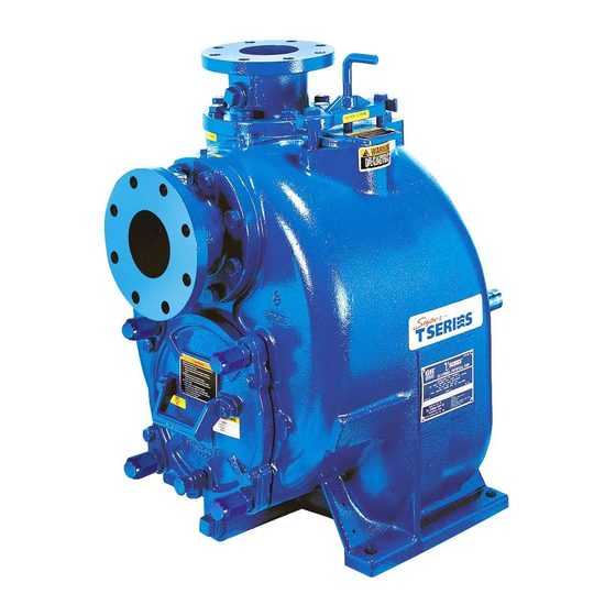
- Page 1 OM-06740-01 February 10, 2015 Rev. B 11‐4‐2022 INSTALLATION, OPERATION, AND MAINTENANCE MANUAL WITH PARTS LIST SUPER T SERIES PUMPS MODELS T8C71SC-B INCLUDING: /F, /FM GORMAN‐RUPP PUMPS www.grpumps.com 2015 Gorman‐Rupp Pumps Printed in U.S.A.
- Page 2 Register your new Gorman‐Rupp pump online at www.grpumps.com/register. Valid serial number and e‐mail address required. RECORD YOUR PUMP MODEL AND SERIAL NUMBER Please record your pump model and serial number in the spaces provided below. Your Gorman‐Rupp distributor needs this information when you require parts or service. Pump Model: Serial Number:...
-
Page 3: Table Of Contents
TABLE OF CONTENTS INTRODUCTION ..........PAGE I - 1 SAFETY - SECTION A . - Page 4 TABLE OF CONTENTS (continued) TROUBLESHOOTING - SECTION D ......PAGE D - 1 PREVENTIVE MAINTENANCE .
-
Page 5: Introduction
SUPER T SERIES OM-06740 INTRODUCTION Thank You for purchasing a Gorman‐Rupp pump. HAZARD AND INSTRUCTION Read this manual carefully to learn how to safely DEFINITIONS install and operate your pump. Failure to do so could result in personal injury or damage to the The following are used to alert maintenance per... -
Page 6: Safety - Section A
SUPER T SERIES OM-06740 SAFETY - SECTION A This information applies to Super T Se which may damage the pump or endan ries basic pumps. Gorman‐Rupp has no ger personnel as a result of pump fail control over or particular knowledge of ure. - Page 7 OM-06740 SUPER T SERIES gaged to be ejected with great force. Al sure within the pump casing can eject low the pump to cool before servicing. these parts with great force when they are disengaged. Allow the pump to completely cool before servicing it. Do not operate the pump against a closed discharge valve for long periods This pump may be used to handle mate...
-
Page 8: Installation - Section B
SUPER T SERIES OM-06740 INSTALLATION - SECTION B Review all SAFETY information in Section A. specific application. Since the pressure supplied to the pump is critical to performance and safety, Since pump installations are seldom identical, this be sure to limit the incoming pressure to 50% of section offers only general recommendations and the maximum permissible operating pressure as practices required to inspect, position, and ar... -
Page 9: Preinstallation Inspection
OM-06740 SUPER T SERIES PREINSTALLATION INSPECTION POSITIONING PUMP Lifting The pump assembly was inspected and tested be Pump unit weights will vary depending on the fore shipment from the factory. Before installation, mounting and drive provided. Check the shipping inspect the pump for damage which may have oc tag on the unit packaging for the actual weight, and curred during shipment. -
Page 10: Line Configuration
SUPER T SERIES OM-06740 compatible with the liquid being pumped. If hose is Fittings used in suction lines, it must be the rigid‐wall, rein Suction lines should be the same size as the pump forced type to prevent collapse under suction. Us inlet. -
Page 11: Suction Line Positioning
OM-06740 SUPER T SERIES of the suction pipe. The baffle will allow entrained critical to efficient pump operation. Figure 2 shows air to escape from the liquid before it is drawn into recommended minimum submergence vs. veloc the suction inlet. ity. -
Page 12: Bypass Lines
SUPER T SERIES OM-06740 In high discharge head applications (more than 30 feet), an excessive amount of liquid may be by passed and forced back to the wet well under the full working pressure of the pump; this will reduce If the application involves a high discharge overall pumping efficiency. -
Page 13: Automatic Air Release Valve
OM-06740 SUPER T SERIES moving the plug to prevent injury to per liters] per minute) will occur when the valve is fully closed. Be sure the bypass sonnel from hot liquid. line is directed back to the wet well or tank to prevent hazardous spills. -
Page 14: Alignment
SUPER T SERIES OM-06740 Align spider insert type couplings by using calipers ALIGNMENT to measure the dimensions on the circumference of the outer ends of the coupling hub every 90 The alignment of the pump and its power source is The coupling is in alignment when the hub ends critical for trouble‐free mechanical operation. - Page 15 OM-06740 SUPER T SERIES tems using two or more belts, make certain that the belts are a matched set; unmatched sets will cause accelerated belt wear. Do not operate the pump without the guard in place over the rotating parts exposed rotating parts can catch cloth...
-
Page 16: Operation - Section C
OM-06740 SUPER T SERIES OPERATION - SECTION C Review all SAFETY information in Section A. Add liquid to the pump casing when: 1. The pump is being put into service for the Follow the instructions on all tags, labels and de first time. -
Page 17: Operation
OM-06740 SUPER T SERIES If rotation is incorrect on a three‐phase motor, have pump components will deteriorate, and a qualified electrician interchange any two of the the liquid could come to a boil, build three phase wires to change direction. If rotation is pressure, and cause the pump casing to incorrect on a single‐phase motor, consult the liter... -
Page 18: Strainer Check
OM-06740 SUPER T SERIES heated pump cautiously. It is recommended that This pump is equipped with an inspection cover to the pressure relief valve assembly be replaced at provide easy access to the interior of the pump for each overhaul, or any time the pump casing over removal of debris and to check the im... -
Page 19: Cold Weather Preservation
OM-06740 SUPER T SERIES liquid during the draining process. Clean out any remaining solids by flushing with a hose. BEARING TEMPERATURE CHECK Do not operate the pump against a closed discharge throttling valve for Bearings normally run at higher than ambient tem long periods of time. - Page 20 SUPER T SERIES OM-06740 TROUBLESHOOTING - SECTION D Review all SAFETY information in Section A. Before attempting to open or service the pump: 1. Familiarize yourself with this manual. 2. Lock out or disconnect the power source to ensure that the pump will remain inoperative.
- Page 21 OM-06740 SUPER T SERIES TROUBLE POSSIBLE CAUSE PROBABLE REMEDY PUMP STOPS OR FAILS Suction intake not submerged at Check installation and correct sub TO DELIVER RATED proper level or sump too small. mergence as needed. FLOW OR PRESSURE Impeller or other wearing parts Replace worn or damaged parts.
- Page 22 SUPER T SERIES OM-06740 equipped) between regularly scheduled inspec PREVENTIVE MAINTENANCE tions can indicate problems that can be corrected Since pump applications are seldom identical, and before system damage or catastrophic failure oc pump wear is directly affected by such things as curs.
- Page 23 PUMP MAINTENANCE AND REPAIR - SECTION E MAINTENANCE AND REPAIR OF THE WEARING PARTS OF THE PUMP WILL MAINTAIN PEAK OPERATING PERFORMANCE. STANDARD PERFORMANCE FOR PUMP MODEL T8C71SC-B, Including /F, /FM Based on 70 F (21 C) clear water at sea level Contact the Gorman‐Rupp Company to verify per...
- Page 24 OM-06740 SUPER T SERIES ILLUSTRATION PARTS PAGE 10 39 Figure 1. Pump Model T8C71SC-B, Including /F, /FM PAGE E - 2 MAINTENANCE & REPAIR...
- Page 25 OM-06740 SUPER T SERIES PARTS LIST Pump Model T8C71SC-B, Including /F, /FM (From S/N 1587621 Up) If your pump serial number is followed by an “N”, your pump is NOT a standard production model. Contact the Gorman‐Rupp Company to verify part numbers.
- Page 26 OM-06740 SUPER T SERIES ILLUSTRATION Figure 2. 44163-333 Repair Rotating Assembly PAGE E - 4 MAINTENANCE & REPAIR...
- Page 27 OM-06740 SUPER T SERIES PARTS LIST 44163-333 Repair Rotating Assembly ITEM PART PART NAME NUMBER IMPELLER 12349 1102H ADJ SHIM SET 5091 17090 CART SEAL ASSY 46513-154 SEAL PLATE 12350 1102H GASKET 12350G 20000 OIL SEAL S1917 OIL SEAL S1917 OIL SEAL S1917 PIPE PLUG...
- Page 28 OM-06740 SUPER T SERIES to ensure that it will remain inoperative. Close all PUMP AND SEAL DISASSEMBLY valves in the suction and discharge lines. AND REASSEMBLY For power source disassembly and repair, consult Review all SAFETY information in Section A. the literature supplied with the power source, or contact your local power source representative.
- Page 29 SUPER T SERIES OM-06740 hardware (20 and 21) and remove the wear plate and wear plate insert (5). Inspect the back cover O‐rings (6 and 7) and re Use Only Genuine Gorman-Rupp re place them if damaged or worn. placement parts. Failure to do so may cre Suction Check Valve Removal ate a hazard and damage the pump or di...
- Page 30 OM-06740 SUPER T SERIES bly has been removed from the pump casing. screws in the jacking holes in the casing ring and use them to press the rotating assembly into the pump casing until the bearing housing is free. Turn Remove the jacking screws from the casing ring.
- Page 31 SUPER T SERIES OM-06740 Seal Removal Pry or press the oil seals (6 and 6A) from the bear ing housing. (Figure 2) After removing the shaft and bearings, clean and Slide the shaft sleeve and rotating portion of the inspect the bearings in place as follows. seal off the shaft as a unit.
- Page 32 OM-06740 SUPER T SERIES housing. Replace the bearings, shaft, or bearing housing if the proper bearing fit is not achieved. If bearing replacement is required, remove the out To prevent damage during removal from board bearing retaining ring (20) and use a bearing the shaft, it is recommended that bearings puller to remove the bearings from the shaft.
- Page 33 SUPER T SERIES OM-06740 movement has occurred, use a suitably sized and 17). Be careful not to damage the oil seal lip sleeve and a press to reposition the bearings on the shaft keyway. against the shaft shoulders. Lubricate the bearing housing as indicated in LU BRICATION.
- Page 34 OM-06740 SUPER T SERIES faces to ensure that they are free of any foreign sleeve O‐ring and the external stationary seat O‐ matter. ring with a very small amount of “P-80 Emul sion” or water. See Figure 6 for seal part identifica To ease installation of the seal, lubricate the shaft tion.
- Page 35 SUPER T SERIES OM-06740 proper clearance as described in Impeller Instal O‐RING ENGAGED WITH SEAL PLATE lation and Adjustment. BORE If necessary to reuse an old seal in an emer gency, carefully separate the rotating and station ary seal faces from the bellows retainer and sta tionary seat.
- Page 36 OM-06740 SUPER T SERIES Slide the rotating portion of the seal (consisting of Proceed with Rotating Assembly Installation be the integral shaft sleeve, spring centering washer, fore installing the impeller capscrew and washer spring, bellows and retainer, and rotating element) (26 and 27).
- Page 37 SUPER T SERIES OM-06740 in the mounting slot in the suction flange (22). Align USE TWO USE TWO REMAINING OPPOSING ADJUSTING SCREWS AND the adaptor with the flange hole and secure the as BACK COVER NUTS LOCKING COLLARS TO SET FACE CLEARANCE TO PRESS sembly with the check valve pin (27).
- Page 38 OM-06740 SUPER T SERIES they engage the pump casing. Install the locking Final Pump Assembly collars (9) and hardware (10 and 11). Reinstall the (Figure 1) back cover nuts. Install the shaft key (22, Figure 2) and reconnect the power source. Be sure to install any guards Be sure the wear plate does not scrape against the used over the rotating members.
- Page 39 SUPER T SERIES OM-06740 Under normal conditions, drain the bearing hous ture condensation. This is especially im ing once each year and refill with approximately 16 portant in areas where variable hot and ounces (0,5 liter) of clean oil. Change the oil more cold temperatures are common.
- Page 40 For Warranty Information, Please Visit www.grpumps.com/warranty or call: U.S.: 419-755-1280 Canada: 519-631-2870 International: +1-419-755-1352 GORMAN‐RUPP PUMPS...
Need help?
Do you have a question about the T8C71SC-B and is the answer not in the manual?
Questions and answers