GORMAN-RUPP PUMPS SUPER T Series Installation, Operation And Maintenance Manual
Hide thumbs
Also See for SUPER T Series:
- Installation, operation and maintenance manual (89 pages) ,
- Installation, operation, and maintenance manual with parts list (49 pages) ,
- Manual (40 pages)
Table of Contents

Related Manuals for GORMAN-RUPP PUMPS SUPER T Series


Summary of Contents for GORMAN-RUPP PUMPS SUPER T Series
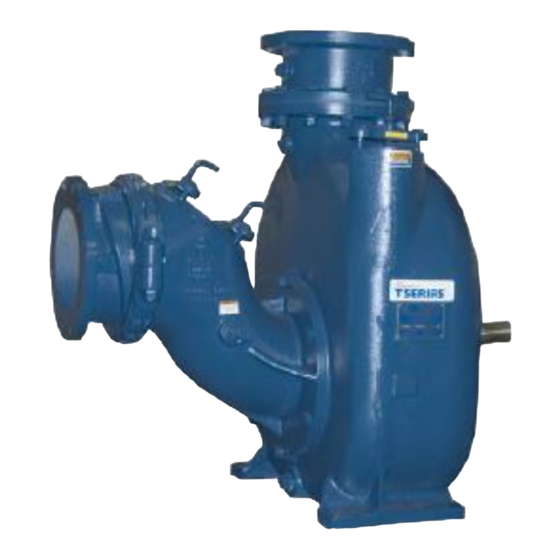
- Page 1 OM‐05519-01 June 25, 2003 Rev. C 07‐10‐14 INSTALLATION, OPERATION, AND MAINTENANCE MANUAL WITH PARTS LIST SUPER T SERIES PUMP MODEL T10A60S-(3/11.5) GORMAN‐RUPP PUMPS www.grpumps.com 2003 Gorman‐Rupp Pumps Printed in U.S.A.
- Page 2 Register your new Gorman‐Rupp pump online at www.grpumps.com Valid serial number and e‐mail address required. The engine exhaust from this product contains chemicals known to the State of California to cause cancer, birth defects or other reproductive harm. RECORD YOUR PUMP MODEL AND SERIAL NUMBER Please record your pump model and serial number in the spaces provided below.
-
Page 3: Table Of Contents
TABLE OF CONTENTS INTRODUCTION ..........PAGE I - 1 SAFETY ‐... - Page 4 TABLE OF CONTENTS (continued) Repair Rotating Assembly ..........PAGE E - 5 Drive Assembly .
-
Page 5: Introduction
SUPER T SERIES OM-05519 INTRODUCTION Thank You for purchasing a Gorman‐Rupp pump. neither operator safety nor pump integrity are com Read this manual carefully to learn how to safely promised by the installation. Pumps and related install and operate your pump. Failure to do so equipment must be installed and operated ac... -
Page 6: Safety - Section A
SUPER T SERIES OM-05519 SAFETY - SECTION A This information applies to Super T Se ger personnel as a result of pump fail ries engine driven pumps. Refer to the ure. manual accompanying the engine be fore attempting to begin operation. - Page 7 OM-05519 SUPER T SERIES Do not remove plates, covers, gauges, Do not operate an internal combustion pipe plugs, or fittings from an over engine in an explosive atmosphere. heated pump. Vapor pressure within the When operating internal combustion pump can cause parts being disen...
-
Page 8: Installation - Section B
SUPER T SERIES OM-05519 INSTALLATION - SECTION B Review all SAFETY information in Section A. Since pump installations are seldom identical, this section offers only general recommendations and Only operate this pump in the direction in practices required to inspect, position, and ar... -
Page 9: Alignment
OM-05519 SUPER T SERIES Clearance necessary and keep personnel away from suspended objects. It is recommended that 18 inches (457 mm) of Pump unit weights will vary depending on the clearance be provided in front of the back cover to mounting and drive provided. -
Page 10: Gauges
SUPER T SERIES OM-05519 to secure them when filled with liquid and under This pump is designed to handle up to 3 inch (76,2 pressure. mm) diameter spherical solids. Sealing Gauges Since even a slight leak will affect priming, head,... -
Page 11: Discharge Lines
OM-05519 SUPER T SERIES reduce the inlet velocity. Calculate the required on the increased opening size (area or diameter). submergence using the following formula based Figure 1. Recommended Minimum Suction Line Submergence vs. Velocity DISCHARGE LINES Siphoning If the application involves a high discharge... -
Page 12: Automatic Air Release Valve
SUPER T SERIES OM-05519 pass line should be at least 1 inch in diameter to the air release piping, it must be a full‐opening ball minimize the chance of plugging. type valve to prevent plugging by solids. In low discharge head applications (less than 30 feet or 9 meters), it is recommended that the by... -
Page 13: Air Release Valve Installation
OM-05519 SUPER T SERIES liters] per minute) will occur when the valve is fully closed. Be sure the bypass line is directed back to the wet well or tank to prevent hazardous spills. É É É When the pump shuts down, the spring returns the diaphragm to its original position. - Page 14 SUPER T SERIES OM-05519 DISCHARGE PIPE CLEAN‐OUT COVER INSTALL AIR RELEASE VALVE IN HORIZONTAL POSITION DISCHARGE CHECK VALVE 90_ LONG RADIUS ELBOW SUPPORT PUMP DISCHARGE BRACKET SELF‐PRIMING CENTRIFUGAL PUMP BLEED LINE 1” (25,4 MM) DIA. MIN. (CUSTOMER FUR NISHED) DO NOT EX...
-
Page 15: Operation - Section C
OM-05519 SUPER T SERIES OPERATION - SECTION C Review all SAFETY information in Section A. liquid in the pump casing. The pump will not prime when dry. extended operation of Follow the instructions on all tags, labels and a dry pump will destroy the seal assembly. -
Page 16: Lines With A Bypass
OM-05519 SUPER T SERIES Do not operate the pump against a A manual shut‐off valve should not be closed discharge throttling valve for installed in any bypass line. A manual long periods of time. If operated against shut‐off valve may inadvertently be left a closed discharge throttling valve, closed during operation. -
Page 17: Strainer Check
OM-05519 SUPER T SERIES As a safeguard against rupture or explosion due to STOPPING heat, this pump is equipped with a pressure relief valve which will open if vapor pressure within the Never halt the flow of liquid suddenly. If the liquid being pumped is stopped abruptly, damaging pump casing reaches a critical point. - Page 18 OM-05519 SUPER T SERIES A sudden increase in bearing temperature is a caused by shaft misalignment and/or excessive vi bration. warning that the bearings are at the point of failing to operate properly. Make certain that the bearing When pumps are first started, the bearings may lubricant is of the proper viscosity and at the cor...
-
Page 19: Troubleshooting - Section D
SUPER T SERIES OM-05519 TROUBLESHOOTING - SECTION D Review all SAFETY information in Section A. Before attempting to open or service the pump: 1. Familiarize yourself with this manual. 2. Shut down the engine and take other precautions to ensure that the pump will remain inoperative. - Page 20 OM-05519 SUPER T SERIES TROUBLE POSSIBLE CAUSE PROBABLE REMEDY PUMP STOPS OR Strainer clogged. Check strainer and clean if neces FAILS TO DELIVER sary. RATED FLOW OR PRESSURE Suction intake not submerged at Check installation and correct sub proper level or sump too small.
-
Page 21: Preventive Maintenance
SUPER T SERIES OM-05519 TROUBLE POSSIBLE CAUSE PROBABLE REMEDY BEARINGS RUN Bearing temperature is high, but Check bearing temperature regu TOO HOT within limits. larly to monitor any increase. Low or incorrect lubricant. Check for proper type and level of lubricant. - Page 22 OM-05519 SUPER T SERIES Preventive Maintenance Schedule Service Interval* Item Daily Weekly Monthly Semi‐ Annually Annually General Condition (Temperature, Unusual Noises or Vibrations, Cracks, Leaks, Loose Hardware, Etc.) Pump Performance (Gauges, Speed, Flow) Bearing Lubrication Seal Lubrication (And Packing Adjustment, If So Equipped) V‐Belts (If So Equipped)
-
Page 23: Pump Maintenance And Repair - Section E
OM-05519 SUPER T SERIES PUMP MAINTENANCE AND REPAIR - SECTION E Maintenance and repair of the wearing parts of the pump will maintain peak operating perfor mance. Hazards or unsafe practices which If your pump serial number is followed by an “N”, COULD result in severe personal injury your pump is NOT a standard production model. - Page 24 OM-05519 SUPER T SERIES ILLUSTRATION PARTS PAGE Figure 1. T10A60S-(3/11.5) Pump End Assembly PAGE E - 2 MAINTENANCE & REPAIR...
-
Page 25: Parts Lists
OM-05519 SUPER T SERIES PARTS LIST T10A60S-(3/11.5) Pump End Assembly (From S/N 1267101 Up) If your pump serial number is followed by an “N”, your pump is NOT a standard production model. Contact the Gorman‐Rupp Company to verify part numbers. - Page 26 OM-05519 SUPER T SERIES ILLUSTRATION Figure 2. 44163-359 Repair Rotating Assembly PAGE E - 4 MAINTENANCE & REPAIR...
- Page 27 OM-05519 SUPER T SERIES PARTS LIST 44163-359 Repair Rotating Assembly ITEM PART MAT'L PART NAME NUMBER CODE IMPELLER 38615-072 11010 CARTRIDGE SEAL ASSY 46513-154 SEAL END PLATE 38272-423 10010 SEAL PLATE GASKET 38684-302 19140 O‐RING 25152-265 HEX HEAD CAP SCREW...
- Page 28 OM-05519 SUPER T SERIES ILLUSTRATION Figure E-3. 44162-172 Drive Assembly PARTS LIST ITEM PART MAT'L PART NAME NUMBER CODE COUPLING KIT 48112-016 -BUSHING 24131-497 -COUPLING ASSEMBLY 24391-102 -LOCKWASHER 21171-536 SAE APPLICATION SOCKET HD CAPSCREW BD0606 15991 HEX HD CAPSCREW B0605...
- Page 29 SUPER T SERIES OM-05519 PUMP AND SEAL DISASSEMBLY AND REASSEMBLY Before attempting to open or service the Review all SAFETY information in Section A. pump: 1. Familiarize yourself with this man Follow the instructions on all tags, label and de...
- Page 30 OM-05519 SUPER T SERIES impeller vanes and the wear plate, and tap the moved from the pump before lifting. Lift wedge with a hammer. Turn the impeller every 45_, the pump or component only as high as repeating the process until the wear plate is necessary and keep personnel away “walked”...
- Page 31 SUPER T SERIES OM-05519 Remove any leveling shims used under the casing Turn mounting feet. Tie and tag the shims for ease of Counterclockwise reassembly. Move the pump end to a clean, well equipped shop Lathe Dog Arm area for further disassembly.
- Page 32 OM-05519 SUPER T SERIES Impeller and Wear Plate Removal When the pump is properly operated and main tained, the bearing housing should not require dis (Figure 2) assembly. Disassemble the shaft and bearings only when there is evidence of wear or damage.
- Page 33 SUPER T SERIES OM-05519 Clean the bearings thoroughly in fresh cleaning Inspect the shaft for distortion, nicks or scratches, solvent. Dry the bearings with filtered compressed or for thread damage on the impeller end. Dress air and coat with light oil.
- Page 34 OM-05519 SUPER T SERIES BALL LOADING BALL LOADING GROOVE POSITIONED GROOVE POSITIONED TOWARD IMPELLER AWAY FROM IMPELLER LOADING LOADING GROOVE GROOVE DIRECTION OF DIRECTION OF THRUST THRUST INSTALLATION OF NEW DEPARTURE OR INSTALLATION OF MRC/SKF 5300M OR BCA/FEDERAL MOGAL 5300W SERIES BEARINGS...
- Page 35 SUPER T SERIES OM-05519 Inspect the seal components for wear, scoring, tilated area free from excessive heat, grooves, and other damage that might cause leak sparks, and flame. Read and follow all age. Inspect the seal area of the impeller shaft, and precautions printed on solvent contain...
- Page 36 OM-05519 SUPER T SERIES If the seal plate was removed, install the seal plate As the stationary seat becomes fully seated, the gasket (4) and bearing housing O‐ring (5). Lubri seal spring compresses, and the shaft sleeve will cate the O‐ring with light grease. Position the seal break the nylon shear ring.
- Page 37 SUPER T SERIES OM-05519 Carefully wash all metallic parts in fresh cleaning to the shaft, making future removal difficult solvent and allow to dry thoroughly. or impossible without damage to the im peller or shaft. Install the same thickness of impeller adjusting shims (32) as previously removed.
- Page 38 OM-05519 SUPER T SERIES ommended for maximum pump efficiency. This NOTE clearance can be obtained by removing an equal If the check valve body was removed, install the amount of shims from each rotating assembly check valve and secure the body to the suction shim set (36) until the impeller scrapes against the head with the shoulder type clamp (33).
- Page 39 SUPER T SERIES OM-05519 Using a suitable lifting device, position the pump ounces (2,5 liters) of SAE No. 30 non‐detergent oil, end so the flexible portion of the coupling seats in or to a level at the middle of the sight gauge (24).
- Page 40 For U.S. and International Warranty Information, Please Visit www.grpumps.com/warranty or call: U.S.: 419-755-1280 International: +1-419-755-1352 For Canadian Warranty Information, Please Visit www.grcanada.com/warranty or call: 519-631-2870 GORMAN‐RUPP PUMPS...
Need help?
Do you have a question about the SUPER T Series and is the answer not in the manual?
Questions and answers