Table of Contents
Advertisement
Quick Links
ACEGU
OM−05297−OE01
June 3, 2002
Rev. A 03-22-10
INSTALLATION, OPERATION,
AND MAINTENANCE MANUAL
WITH PARTS LIST
80 SERIES PUMP
MODELS
82D1−GX160
82D1−(GX160) PPO
THE GORMAN-RUPP COMPANY D MANSFIELD, OHIO
www.grpumps.com
D
GORMAN-RUPP OF CANADA LIMITED
ST. THOMAS, ONTARIO, CANADA
Printed in U.S.A.
e
2002 The Gorman-Rupp Company
Advertisement
Table of Contents

Related Manuals for GORMAN-RUPP PUMPS 82D1 GX160


Summary of Contents for GORMAN-RUPP PUMPS 82D1 GX160
- Page 1 ACEGU OM−05297−OE01 June 3, 2002 Rev. A 03-22-10 INSTALLATION, OPERATION, AND MAINTENANCE MANUAL WITH PARTS LIST 80 SERIES PUMP MODELS 82D1−GX160 82D1−(GX160) PPO THE GORMAN-RUPP COMPANY D MANSFIELD, OHIO www.grpumps.com GORMAN-RUPP OF CANADA LIMITED ST. THOMAS, ONTARIO, CANADA Printed in U.S.A. 2002 The Gorman-Rupp Company...
- Page 2 Register your new Gorman-Rupp pump online at www.grpumps.com Valid serial number and e-mail address required. The engine exhaust from this product contains chemicals known to the State of California to cause cancer, birth defects or other reproductive harm. RECORD YOUR PUMP MODEL AND SERIAL NUMBER Please record your pump model and serial number in the spaces provided below.
-
Page 3: Table Of Contents
TABLE OF CONTENTS INTRODUCTION ..........PAGE I −... - Page 4 TABLE OF CONTENTS (continued) Pump Parts Only ............PAGE E −...
-
Page 5: Introduction
80 SERIES OM−05297 INTRODUCTION Thank You for purchasing a Gorman-Rupp pump. For information or technical assistance on the en- Read this manual carefully to learn how to safely gine, contact the engine manufacturer’s local install and operate your pump. Failure to do so dealer or representative. -
Page 6: Safety - Section A
80 SERIES OM−05297 SAFETY - SECTION A This information applies to 80 Series en- sive, or flammable liquids which may gine driven pumps. Refer to the manual damage the pump or endanger person- accompanying the engine before at- nel as a result of pump failure. tempting to begin operation. - Page 7 OM−05297 80 SERIES Fuel used by internal combustion en- Never tamper with the governor to gain gines presents an extreme explosion more power. The governor establishes and fire hazard. Make certain that all safe operating limits that should not be fuel lines are securely connected and exceeded.
-
Page 8: Installation − Section Bpage B
80 SERIES OM−05297 INSTALLATION − SECTION B Review all SAFETY information in Section A. specific application. Since the pressure supplied to the pump is critical to performance and safety, Since pump installations are seldom identical, this be sure to limit the incoming pressure to 50% of the section offers only general recommendations and maximum permissible operating pressure as practices required to inspect, position, and ar-... -
Page 9: Positioning Pump
OM−05297 80 SERIES ing, check for loose hardware at mating sur- The pump may have to be supported or shimmed faces. to provide for level operation or to eliminate vibra- tion. c. Carefully read all tags, decals, and markings To ensure sufficient lubrication and fuel supply to on the pump assembly, and perform all duties the engine, do not position the pump and engine indicated. -
Page 10: Gauges
80 SERIES OM−05297 lines are used, they should have adequate support This pump is designed to handle up to 5/8 inch to secure them when filled with liquid and under (15,9 mm) diameter spherical solids. pressure. Sealing Gauges Since even a slight leak will affect priming, head, and capacity, especially when operating with a Most pumps are drilled and tapped for installing high suction lift, all connections in the suction line... -
Page 11: Discharge Lines
OM−05297 80 SERIES submergence using the following formula based on the increased opening size (area or diameter). Figure 2. Recommended Minimum Suction Line Submergence vs. Velocity DISCHARGE LINES stalled in the discharge line to protect the pump from excessive shock pressure and reverse rota- tion when it is stopped. -
Page 12: Operation − Section C
OM−05297 80 SERIES OPERATION − SECTION C Review all SAFETY information in Section A. Add liquid to the pump casing when: Follow the instructions on all tags, labels and 1. The pump is being put into service for the decals attached to the pump. first time. -
Page 13: Operation
OM−05297 80 SERIES Liquid Temperature And Overheating OPERATION The maximum liquid temperature for this pump is 160_ F (71_C). Do not apply it at a higher operating temperature. Overheating can occur if operated with the valves Pump speed and operating condition in the suction or discharge lines closed. -
Page 14: Stopping
OM−05297 80 SERIES Open the suction line, and read the vacuum gauge After stopping the pump, remove the spark plug with the pump primed and at operation speed. wire to ensure that the pump will remain inopera- Shut off the pump. The vacuum gauge reading will tive. -
Page 15: Troubleshooting − Section Dpage D
80 SERIES OM−05297 TROUBLESHOOTING − SECTION D Review all SAFETY information in Section A. Before attempting to open or service the pump: 1. Familiarize yourself with this manual. 2. Shut down the engine and disconnect the spark plug wire or take other pre- cautions to ensure that the pump will remain inoperative. - Page 16 OM−05297 80 SERIES TROUBLE POSSIBLE CAUSE PROBABLE REMEDY PUMP STOPS OR Air leak in suction line. Correct leak. FAILS TO DELIVER Lining of suction hose collapsed. Replace suction hose. RATED FLOW OR PRESSURE Leaking or worn seal or pump gasket. Check pump vacuum.
-
Page 17: Preventive Maintenance Page D
80 SERIES OM−05297 equipped) between regularly scheduled inspec- PREVENTIVE MAINTENANCE tions can indicate problems that can be corrected Since pump applications are seldom identical, and before system damage or catastrophic failure oc- pump wear is directly affected by such things as curs. -
Page 18: Pump Maintenance And Repair - Section Epage E
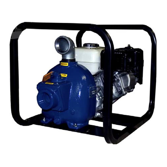
80 SERIES OM−05297 PUMP MAINTENANCE AND REPAIR - SECTION E MAINTENANCE AND REPAIR OF THE WEARING PARTS OF THE PUMP WILL MAINTAIN PEAK OPERATING PERFORMANCE. STANDARD PERFORMANCE FOR PUMP MODELS 82D1−GX160 Based on 70_ F (21_ C) clear water at sea level with minimum suction lift. - Page 19 OM−05297 80 SERIES SECTION DRAWING PARTS PAGE Figure 1. Pump Model 82D1−GX160 PAGE E − 2 MAINTENANCE & REPAIR...
-
Page 20: Parts Lists
80 SERIES OM−05297 PARTS LIST Pump Model 82D1−GX160 (From S/N 1257391 up) If your pump serial number is followed by an N", your pump is NOT a standard production model. Contact the Gorman-Rupp Company to verify part numbers. ITEM PART MAT’L PART NAME NUMBER... - Page 21 OM−05297 80 SERIES SECTION DRAWING Figure 2. 82D1−(GX160) PPO PAGE E − 4 MAINTENANCE & REPAIR...
- Page 22 80 SERIES OM−05297 PARTS LIST 82D1−(GX160) PPO ITEM PART NAME PART MAT’L ITEM PART NAME PART MAT’L NUMBER CODE NUMBER CODE PUMP CASING 6846C 13040 HEX HD CAPSCREW B0414 15991 FLAT WASHER KF04 18040 IMPELLER 2912F 11010 STUD C0606 15991 SEAL ASSY 25285−853 −−−...
- Page 23 OM−05297 80 SERIES PUMP AND SEAL DISASSEMBLY 3. Allow the pump to completely cool if overheated. AND REASSEMBLY 4. Check the temperature before opening any covers, plates, or Review all SAFETY information in Section A. plugs. 5. Close the suction and discharge Follow the instructions on all tags, label and de- valves.
- Page 24 80 SERIES OM−05297 gage the hardware (15, 16, 18 and 19) and pull the wear plate from the pump casing. Impeller Removal Most cleaning solvents are toxic and flammable. Use them only in a well ven- (Figure 2) tilated area free from excessive heat, sparks, and flame.
- Page 25 OM−05297 80 SERIES INTERMEDIATE SPRING SPRING RETAINER SHAFT IMPELLER SLEEVE SHIMS ENGINE CRANKSHAFT STATIONARY IMPELLER SEAT BELLOWS STATIONARY ELEMENT ROTATING ELEMENT RETAINER Figure 3. Seal Assembly bricated shaft sleeve until the rotating element is just flush with the chamfered end of the sleeve. Slide the sleeve over the shaft until the sealing faces contact.
- Page 26 80 SERIES OM−05297 Pump Casing Installation Position the check valve assembly (22) in the suc- tion port with the large weight toward the inside of (Figure 2) the pump casing. Install the suction flange (30), and secure with the nuts (21). Check the operation If the wear plate (14) was removed for replace- of the check valve to ensure proper seating and ment, secure it to the pump casing using the at-...
- Page 27 For U.S. and International Warranty Information, Please Visit www.grpumps.com/warranty or call: U.S.: 419−755−1280 International: +1−419−755−1352 For Canadian Warranty Information, Please Visit www.grcanada.com/warranty or call: 519−631−2870 THE GORMAN-RUPP COMPANY D MANSFIELD, OHIO GORMAN-RUPP OF CANADA LIMITED ST. THOMAS, ONTARIO, CANADA...
Need help?
Do you have a question about the 82D1 GX160 and is the answer not in the manual?
Questions and answers