
Related Manuals for wtw IQ SENSOR NET NiCaVis 705 IQ NI


Summary of Contents for wtw IQ SENSOR NET NiCaVis 705 IQ NI
- Page 1 Operating manual IQ S ENSOR NiCaVis 701 IQ NI NiCaVis 705 IQ NI NiCaVis 701 IQ NI Optical sensor for the NiCaVis 705 IQ NI spectral determination of nitrite, nitrate and carbon sum parameters ba75988e01 11/2012...
- Page 2 The latest version of the present operating manual can be found on the Internet at www.WTW.com. © Copyright Weilheim 2012, WTW GmbH Reprinting - even as excerpts - is only allowed with the explicit written authorization of WTW GmbH, Weilheim. Printed in Germany. ba75988e01 11/2012...
-
Page 3: Table Of Contents
NiCaVis 70x IQ NI Contents NiCaVis 70x IQ NI - Contents Overview ........3-1 How to use this component operating manual . - Page 4 CarboVis 70x IQ TS Maintenance and cleaning ..... . .7-1 Maintenance ........7-1 Sensor cleaning .
-
Page 5: Overview
Overview NiCaVis 70x IQ NI Overview How to use this component operating manual Structure of the operating IQ S IQ Sensor Net Operating Manual ENSOR manual System Operating Manual (Ring Binder) IQ Sensor MIQ Module MIQ Terminal Operating Operating Operating Manual Manual Manual... -
Page 6: Fields Of Application
Overview NiCaVis 70x IQ NI Fields of application The NiCaVis 70x IQ NI is an online sensor for the on-site determination of nitrite, nitrate and carbon sum parameters in waste water treatment plants. The range of application comprises control, feedback control and mon- itoring. -
Page 7: Structure Of The Uv Sensor
Overview NiCaVis 70x IQ NI Structure of the UV sensor A UV sensor contains a light source (1), a measuring gap (3) to enable the contact of light with the measuring solution, and a detector (5) to measure the attenuated light beam. The sender of the optical system (2) directs a light beam, the measuring beam (6), through the measuring solution and a second light beam, the reference beam (8), over a distance without measuring solution. - Page 8 Overview NiCaVis 70x IQ NI 1 - 4 ba75988e01 11/2012...
-
Page 9: Safety
Safety CarboVis 70x IQ TS Safety Safety information 2.1.1 Safety information in the operating manual This operating manual provides important information on the safe operation of the product. Read this operating manual thoroughly and make yourself familiar with the product before putting it into operation or working with it. The operating manual must be kept in the vicinity of the meter so you can always find the infor- mation you need. -
Page 10: Safe Operation
Safety CarboVis 70x IQ TS Safe operation 2.2.1 Authorized use The authorized use of the NiCaVis 70x IQ NI consists of its use as a sensor in the IQ S . Only the operation and running of the product according to ENSOR the instructions and technical specifications given in this operating manual is authorized (see chapter 8 T... -
Page 11: Commissioning
Commissioning NiCaVis 70x IQ NI Commissioning IQ S system requirements ENSOR Software statuses of the The operation of the NiCaVis 70x IQ NI requires the following software controller and terminal versions in the IQ S ENSOR components DIQ/S 182 Controller software: Version 3.45 or higher ... -
Page 12: Installation
Commissioning NiCaVis 70x IQ NI Installation 3.3.1 Mounting the sensor Note The sensor is an optical precision instrument that is to be protected against shocks. Make sure the distances to the wall, bottom and other installation surroundings are sufficient. If necessary, protect the sensor from hitting with the protective ring provided. - Page 13 Commissioning NiCaVis 70x IQ NI Vertical installation For vertical installation, mount the sensor in a position that allows inter- fering elements in the measuring gap to escape with the current. In the case of vertical installation, the minimum flow rate is 0.2 m/s so the measuring gap is kept clean optimally.
-
Page 14: Mounting The Shock Protectors
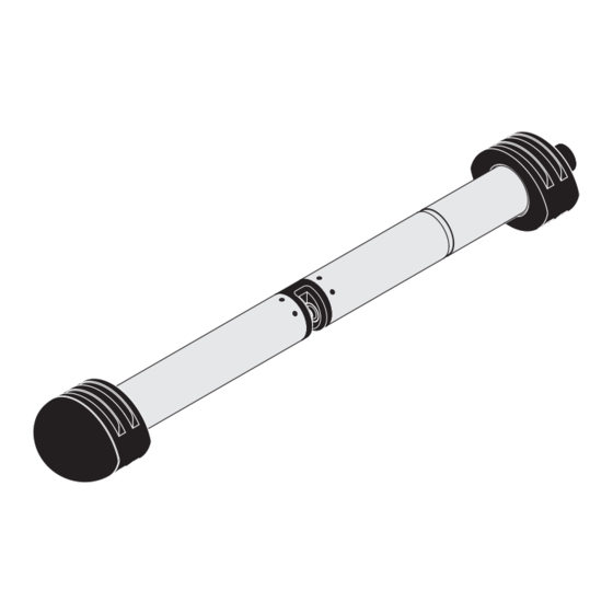
Commissioning NiCaVis 70x IQ NI 3.3.2 Mounting the shock protectors The shock protectors consist of two rings, a cap and four cable ties. To mount the shock protectors, proceed as follows: Sensor with mounted shock protectors Fig. 3-4 Mounting the shock protectors Plug the cap (pos. -
Page 15: Connecting The Sensor To The Iq S
NiCaVis 70x IQ NI . Information on this and other IQ S ENSOR accessories is given in the WTW catalog and on the Internet. How to connect the SACIQ (SW) sensor connection cable to the termi- nal strip of an MIQ module is described in chapter 3 I... - Page 16 Commissioning NiCaVis 70x IQ NI Connecting the sensor to Take the protective caps off the plug connections of the sensor the sensor connection and the SACIQ (SW) sensor connection cable and keep them cable safe. Plug the socket of the SACIQ (SW) sensor connection cable onto the plug head connector of the sensor.
-
Page 17: Initial Commissioning
Commissioning NiCaVis 70x IQ NI Initial commissioning 3.4.1 General information CAUTION Never look into the measuring window or put objects into the measur- ing window during operation! The emitted UV radiation can damage the eyes! In the case of authorized use, inadvertent eye contact with the light beam is not possible. -
Page 18: Sensor Structure
Commissioning NiCaVis 70x IQ NI 3.4.2 Sensor structure The physical sensor is the sensor with the instrument or model desig- nation, NiCaVis 70x IQ NI. The physical sensor processes the mea- surement signal (absorbance spectrum) and supplies up to 5 measurement results to the IQ S . -
Page 19: Settings For The Main Sensor
Commissioning NiCaVis 70x IQ NI 3.4.3 Settings for the main sensor Measuring cycle A measuring cycle consists of the cleaning procedure, the adjustment time for the measuring system and the determination of the measured value. The following graphic demonstrates the relevant settings: Measuring cycle Time... - Page 20 Commissioning NiCaVis 70x IQ NI Menu item Settings Explanations Measuring location NiCaVis 701 IQ NI Measurement location or application of Activation the sensor. The possible measurement loca- Inlet tions are displayed depending on the Outlet currently set measuring mode. NiCaVis 705 IQ NI ...
- Page 21 Commissioning NiCaVis 70x IQ NI Menu item Settings Explanations Response time t90 10 ... 60 min Response time of the signal smoothing. Depending on the sample matrix, mea- sured values can vary more or less strongly (e.g. due to foreign bodies or air bubbles).
-
Page 22: Settings For Virtual Sensors
Commissioning NiCaVis 70x IQ NI 3.4.4 Settings for virtual sensors Carrying out settings Using <S>, switch from the measured value display to the main menu of the settings. Then navigate to the setting menu (setting table) of the sensor. The procedure is described in detail in your IQ S ENSOR system operating manual. - Page 23 Commissioning NiCaVis 70x IQ NI Menu item Settings Explanations Main sensor Information that there are further sen- sor overlapping settings in the setting menu of the relevant main sensor Meas. interval Cleaning duration nal smoothing etc.). Save and quit The system confirms the saving of the settings and the display switches to the next higher level.
- Page 24 Commissioning NiCaVis 70x IQ NI 3 - 14 ba75988e01 11/2012...
-
Page 25: Measuring / Operation
Measuring / Operation NiCaVis 70x IQ NI Measuring / Operation Determination of measured values Physical sensor, series number xxx Absorbance spectrum Absorbance spectrum of zero adjustment of measurement Main Virtual sensor sensor software software Main sensor meas. mode Virtual sensor meas. mode (algorithm) (algorithm) Main sensor raw value... -
Page 26: Measuring Operation
Measuring / Operation NiCaVis 70x IQ NI Measuring operation CAUTION Never look into the measuring window or put objects into the measur- ing window during operation! The emitted UV radiation can damage the eyes! In the case of authorized use, inadvertent eye contact with the light beam is not possible. -
Page 27: Calibration
Measuring / Operation NiCaVis 70x IQ NI Calibration 4.3.1 Overview In the delivery condition, the sensor is precalibrated and ready to mea- sure (see section 3.4.1). There are two types of calibration that are included into the calculation of the measured value at different points (see section 4.1): ... - Page 28 Measuring / Operation NiCaVis 70x IQ NI Sensor check (H2O dest.) The characteristics of a sensor and thus the measured values provided by it change in the course of time. The reasons for this can be the aging of the sensor, or contamination or mechanical damage of the sensor.
- Page 29 Measuring / Operation NiCaVis 70x IQ NI 4.3.2 User calibration Calibration points and The adjustment is carried out at one or two points within the measuring value pairs range. A value pair is determined at each point. Each value pair consists of the raw value of the UV sensor and the corresponding refer- ence value.
- Page 30 Measuring / Operation NiCaVis 70x IQ NI Performing a user Proceed as follows if you want to perform a user calibration: calibration Settings of sensors and diff. sensors Signal In the menu, set the smoothing setting to Save and quit Subsequently, leave the menu with Settings of sensors and diff.
- Page 31 Measuring / Operation NiCaVis 70x IQ NI Default values are marked in bold. Menu item Settings Explanations Cal - # raw value 1 0.00 ... 5000.00 Raw value of the first value pair (lower concentration). For single-point calibration, enter 0. Cal - ref.
- Page 32 Measuring / Operation NiCaVis 70x IQ NI Zero adjustment 4.3.3 Sensor check/ Note The sensor check or Zero adjustment must be carried out under abso- lutely clean conditions. If you do not work carefully enough the Zero ad- justment can deteriorate the measuring quality. Ultrapure water As ultrapure water exclusively use distilled or deionized water that is (H2O dist.)
- Page 33 Measuring / Operation NiCaVis 70x IQ NI Flowchart Cleaning the sensor Sensor check (H2O dist.) Clean the measurement windows Assessment number Rinse the measuring chamber -40 ... +40 < -40 or with ultrapure water several times > +40 Carry out a sensor check (H2O) After cleaning several times without significant change of the sensor assesssment:...
- Page 34 Measuring / Operation NiCaVis 70x IQ NI Zero adjustment Preparing the sensor Prepare the sensor check or as follows: check or Zero adjustment Switch to the measured value display with <M>. Use <> to select the UV sensor. Maintenance condition: Call up calibration with <C>.
- Page 35 Measuring / Operation NiCaVis 70x IQ NI Measuring chamber Sensor sleeve Fig. 4-5 Putting the sensor sleeve on the sensor Put the sensor in a horizontal position on a firm and vibration- free surface. Turn the filling opening of the sensor sleeve upward (Fig.
- Page 36 Measuring / Operation NiCaVis 70x IQ NI Start measurement Confirm each checklist with <OK> until the display appears. Up to this point, you can break off the calibration procedure at any time with the <ESC> key. The system continues to work with the old calibra- tion data.
- Page 37 Measuring / Operation NiCaVis 70x IQ NI If no valid zero adjustment is possible under the current conditions, you can restore the readiness for measurement by measuring with an older valid zero adjustment. Zero adjustment To do so, select the setting in the sensor settings Factory User...
- Page 38 Measuring / Operation NiCaVis 70x IQ NI 4 - 14 ba75988e01 11/2012...
-
Page 39: Maintenance And Cleaning
Maintenance and cleaning NiCaVis 70x IQ NI Maintenance and cleaning Maintenance The UV NiCaVis 70x IQ NI sensor operates maintenance-free. Sensor cleaning 5.2.1 Cleaning agents and accessories Cleaning agents To clean the sensor, use the following cleaning agents only: Contamination Cleaning agents Water-soluble substances –... -
Page 40: General Steps To Be Taken
Maintenance and cleaning NiCaVis 70x IQ NI 5.2.2 General steps to be taken Depending on the application site and the level of contamination of the sensor as well as the coming job, the cleaning procedure includes the following parts: Every cleaning procedure starts with a basic cleaning. It removes tough grime such as incrustation of fouling matter, algae and biolog- ical deposits. -
Page 41: Basic Cleaning
Maintenance and cleaning NiCaVis 70x IQ NI 5.2.3 Basic cleaning Steps of the basic Take the sensor out of the test sample and remove any solid cleaning matter deposits and incrustation of fouling matter manually with a brush or sponge. Wash the sensor down with warm tapwater (30 - 50 °C). -
Page 42: Cleaning The Measuring Gap
Maintenance and cleaning NiCaVis 70x IQ NI 5.2.4 Cleaning the measuring gap To remove lime or grease deposits, use the flocked cleaning cards together with the following detergents: Contamination Cleaning agents Lime deposits Hydrochloric acid 5 % for analysis Grease deposits Mixture of isopropanol and water (approx. -
Page 43: Spare Parts, Maintenance Equipment, Accessories
Spare parts, maintenance equipment, accessories NiCaVis 70x IQ NI Spare parts, maintenance equipment, accessories General accessories, Description Model Order no. replacement parts Calibration sleeve VIS/CV 481 074 20 flocked cleaning cards for VIS/CT 481 071 cleaning the measuring gap Cleaning set: VIS C/SET 481 079 –... - Page 44 VIS Set/EH 481 073 lation with EH/F 170 swing mount- ing assembly Flow-through armature VIS FT-1 480 080 Information on other IQ S accessories is given in the WTW ENSOR catalog and on the Internet. 6 - 2 ba75988e01 11/2012...
-
Page 45: What To Do If
Sensor check (standard) Sensor check (standard) defective Check conditions, especially cleanliness (section 4.3.3) Zero adjustment – still errone- – Contact WTW ous after several trials – Unknown – See log book Implausible measured Cause Remedy values – Erroneous user calibration –... - Page 46 What to do if... NiCaVis 70x IQ NI Drifting measured values Cause Remedy – Cleaning efficiency too low - – Clean the measurement win- measurement windows dows (section 5.2.4) becoming more and more – Use other cleaning method contaminated – Select different measurement location –...
- Page 47 What to do if... NiCaVis 70x IQ NI Measured values too low Cause Remedy or too high – Gas bubbles in front of the – Check the installation position measurement windows of the sensor – Measurement windows dirty – Clean the measurement win- dows ERROR Display of...
- Page 48 What to do if... NiCaVis 70x IQ NI 7 - 4 ba75988e01 11/2012...
-
Page 49: Technical Data
Technical data NiCaVis 70x IQ NI Technical data Measurement characteristics Measuring principle Spectrophotometric absorption measurement; integrated micropro- cessor electronics, shielded 2-wire connection for power and data transmission. Wavelength range 200 - 390 nm NiCaVis 701 IQ NI 1 mm Measuring gap (optical NiCaVis 705 IQ NI 5 mm layer thickness) - Page 50 Technical data NiCaVis 70x IQ NI Carbon measurement, Measuring Measuring mode Measuring range Resolution 1 mm gap width location Inlet COD spectr., total 0 ... 20000 mg/L 1 mg/L COD spectr., dissolv 0 ... 12500 mg/L 1 mg/L TOC spectr., correl. 0 ...
-
Page 51: Application Conditions
Technical data NiCaVis 70x IQ NI Carbon measurement, Measuring Measuring mode Measuring range Resolution 5 mm gap width location Outlet COD spectr., total 0.0 ... 800.0 mg/L 0.1 mg/L COD spectr., dissolv 0.0 ... 800.0 mg/L 0.1 mg/L TOC spectr., correl. 0.0 ... - Page 52 Technical data NiCaVis 70x IQ NI Immersion depth The measuring gap must be filled with test sample. 10 m depth Operating position 8 - 4 ba75988e01 11/2012...
-
Page 53: General Data
Technical data NiCaVis 70x IQ NI General data Dimensions hock protection: (in mm) Ø 96 Socket SACIQ... Ø 60 With shock protection: Ø 96 Weight Approx. 3.8 kg (without shock protectors and without sensor connec- tion cable) Approx. 4.8 kg (with shock protectors but without sensor connection cable) Connection technique Connection via SACIQ (SW) sensor connection cable... -
Page 54: Electrical Data
Technical data NiCaVis 70x IQ NI Instrument safety Applicable norms – EN 61010-1 – UL 61010-1 – CAN/CSA C22.2#61010-1 – IEC 62471 Test certificates cETLus, CE Conforms to ANSI/UL 61010-1 Certified to CAN/CSA C22.2#61010-1" 2001759 Electrical data Nominal voltage Max. 24VDC via the IQ S (for more ENSOR... -
Page 55: Indexes
Indexes NiCaVis 70x IQ NI Indexes Explanation of the messages This chapter contains a list of all the message codes and related message texts that can occur in the log book of the IQ S ENSOR system for the NiCaVis 70x IQ NI. Information on the contents and structure of the log book and the struc- ture of the message code is given in the L chapter of the... -
Page 56: Error Messages
Indexes NiCaVis 70x IQ NI 9.1.1 Error messages Message code Message text Sensor temperature too high! EA2541 * Check process and application Sensor temperature too low! EA3541 * Check process and application Zero adjustment erroneous EAI541 * Clean the sensor and sensor sleeve repeatedly * Position the sensor sleeve according to operating manual * Rinse the measuring chamber with ultrapure water several times * Fill the measuring chamber with ultrapure water... - Page 57 Indexes NiCaVis 70x IQ NI Message code Message text Failure optical measurement: hardware ES5541 * Contact service Failure optical measurement: software ES6541 * Contact service Failure optical measurement: software BIOS ES7541 * Contact service ba75988e01 11/2012 9 - 3...
-
Page 58: Info Messages
Indexes NiCaVis 70x IQ NI 9.1.2 Info messages Message code Message text Zero adjustment was successfully carried out IAC541 * Carry out sensor check * If required, carry out new user calibration The factory zero adjustment was activated. Make sure the sensor op IC3541 erates correctly. -
Page 59: Status Info
Indexes NiCaVis 70x IQ NI Status info The status info is a coded piece of information on the current status of a sensor. Each sensor sends this status info to the controller. The sta- tus info of sensors consists of 32 bits, each of which can have the value 0 or 1. - Page 60 Indexes NiCaVis 70x IQ NI 9 - 6 ba75988e01 11/2012...
-
Page 61: Appendix: Glossary
Appendix: Glossary NiCaVis 70x IQ NI Appendix: Glossary Resolution Smallest difference between two measured values that can be displayed by a meter. BSB, BOD Abbreviation for the "Biochemical Oxygen Demand". The biochemical oxygen demand of the amount of oxygen required by microorganisms in order to aerobically decompose organic substances in an aqueous solution. - Page 62 Appendix: Glossary NiCaVis 70x IQ NI Measuring gap The measuring gap is between the two measurement windows. In the measuring gap, the light beam penetrates the test sample. Measured value The measured value is the special value of a measured parameter to be determined.
- Page 64 Wissenschaftlich-Technische Werkstätten GmbH Dr.-Karl-Slevogt-Straße 1 D-82362 Weilheim Germany Tel: +49 (0) 881 183-0 +49 (0) 881 183-100 Fax: +49 (0) 881 183-420 E-Mail: Info@WTW.com Internet: http://www.WTW.com...
Need help?
Do you have a question about the IQ SENSOR NET NiCaVis 705 IQ NI and is the answer not in the manual?
Questions and answers