Table of Contents
Advertisement
Quick Links
Wiring / Owner's
Manual
Use this manual for circuit board 4302-018 Revision A or higher.
Entrapment Protection must be provided for the gate system where the risk of entrapment or obstruction exists. The operator
will NOT run without one or more monitored type B1 or B2 entrapment protection devices in EACH entrapment area.
UL 325 August 2018 Standard
6 4
6 0
6 0
THIS PRODUCT IS TO BE INSTALLED AND SERVICED BY A TRAINED GATE/DOOR SYSTEMS TECHNICIAN ONLY.
Visit www.doorking.com/dealer-locator to find a professional installing and servicing dealer in your area.
Installer: Leave manual with property owner.
Date Installed:
Installer/Company Name:
Phone Number:
Property Owner: Checklist in back of manual to review and verify new installation with Installer.
Conforms To UL STD 325
Certified To CSA STD C22.2 # 247
4302-065-F-2-21
115 VAC Control Boxes for
115 VAC Control Boxes for
115 VAC Control Boxes for
0 0
0 4
D
O
O
R
K
I
N
G
0 6
Copyright 2021 DoorKing
6004, 6006 and 6400 gate operators
S t a
n d
C o
W A
a r d
n t r
o l
I n c
l u d
B o
8 0
e s
G
V I N
S I
M O
4 0
O U
D o
R I
S E
x
te
- 0 8
g a
p e
o r K
te
e ra
o f
O p
e e
d fr
a n
w
ll o
T w
t a
g a
0 r
n o
i n g
te
D o
e ra
o p
d in
o r
o s
ta n
a d
t s
g a
n o
il e
D o
w h
th
p a
r' s
n e
M i
i n g
i o
o w
a d
R e
c r o
r e c
l e
P l u
e i v
b u
t t o
s t
e r .
O R
N F
C O
r a n
n
S I/
A N
R T
C E
C 2
s m
S A
N /C
C A
U L
i t t e
H IC
V E
S
A S
C L
r s .
L
D E
M O
L
R IA
S E
S
L T
V O
P S
A M
E L
A T
X G
M A
in g
o rK
D o
Circuit Board
Serial Number
and Revision Letter:
®
, Inc. All rights reserved.
4302-065-F-2-21
G
I N
R N
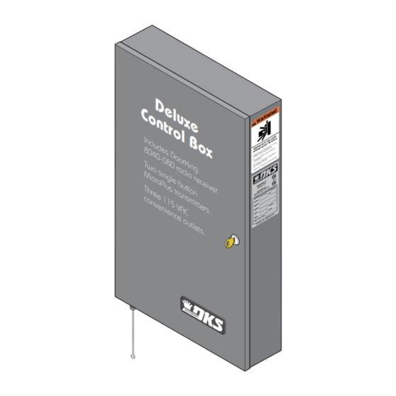
D e
C o
l u x
E
U S
n t r
C A
T H
E A
N
e
C A
R D
T E
h t
Y O
G A
s ig
U R
in
a is
N J
a re
s .
o n
o l
g a
te
c ti
tr u
a
e n
a re
w h
b s
d o
g a
te
ly
o n
a n
y in
le
o p
p la
u g
h
to
re n
th ro
il d
lk
c h
w a
s .
B o
o r
te .
o n
th
c ti
I n c
p a
tr u
g .
in s
g a
te
v in
m o
ty
a fe
is
d s
l u d
te
a n
a l
n u
m a
8 0
e s
4 0
D o
- 0 8
o r K
2
38
53
T O
M S
T w
0 r
-3 2
5
i n g
U L
4 7
O R
o s
T O
a d
. 2
A T
D
N O
IF IE
E R
2 .2
O P
T E
M i
i n g
i o
G A
H P
A R
c r o
l e
P l u
b u
E
A S
P H
t t o
T h r
s t
H z
6 0
r a n
e e
C A
d ,
D
o o
O A
s m
le w
c o n
1 1
In g
c .,
, In
5 V
v e
n i e
A C
n c e
o u
t l e
D o
R e
o r K
t r o
i n g
- R e
8 0
f l e
c t i v
I n c
l u d
Copyright 2009 DoorKing, Inc. All rights reserved.
G
I N
R N
W A
E
U S
C A
T H
N
E A
C A
R D
T E
h t
Y O
G A
s ig
x
in
U R
G
a is
V I N
N J
a re
s .
S I
te
o n
M O
g a
c ti
O U
e n
tr u
a
b s
a re
R I
w h
te
d o
g a
S E
o n
ly
a n
y in
te
le
g a
o p
p la
h
te
p e
to
u g
e ra
o f
re n
th ro
O p
e e
il d
d fr
c h
w a
lk
s .
a n
w
te .
o r
o n
ll o
c ti
t a
g a
p a
th
n o
g .
tr u
te
te
in s
D o
e ra
g a
v in
o p
m o
ty
o r
d in
a fe
ta n
is
d s
te
t s
g a
a n
n o
il e
a l
n u
D o
w h
m a
p a
th
r' s
n e
o w
a d
R e
r e c
2
e i v
38
53
T O
M S
5
O R
-3 2
N F
e r .
U L
C O
S I/
A N
T O
4 7
O R
. 2
A T
D
n
IF IE
N O
E R
R T
2 .2
O P
C E
C 2
T E
S A
G A
H P
N /C
A R
C A
U L
H IC
V E
i t t e
S
A S
C L
L
E
D E
A S
r s .
P H
M O
L
H z
R IA
6 0
S E
L T
S
V O
C A
d ,
D
o o
P S
O A
E L
le w
A M
In g
A T
X G
c .,
M A
, In
in g
o rK
D o
t s .
8 0
- 0 5
e P
7
h o
e d
t o c
e l l
1
Advertisement
Table of Contents
Troubleshooting

Related Manuals for DKS 6006


Summary of Contents for DKS 6006
- Page 1 115 VAC Control Boxes for 115 VAC Control Boxes for Manual 6004, 6006 and 6400 gate operators Use this manual for circuit board 4302-018 Revision A or higher. 4302-065-F-2-21 Entrapment Protection must be provided for the gate system where the risk of entrapment or obstruction exists. The operator will NOT run without one or more monitored type B1 or B2 entrapment protection devices in EACH entrapment area.
-
Page 2: Quick Guide: Dip Switches
Same opening directions as illustrated above for the primary operator type. Direction of • Switch 2 will be the SAME setting as switch 1 for the 6006. SECONDARY • Switch 2 will be the OPPOSITE setting as switch 1 for the 6004 and 6400. -
Page 3: Quick Guide: Terminal Description
QUICK GUIDE: Terminal Description For specific wiring information, see page 15. 2 3 4 5 6 7 8 9 10 11 12 13 14 15 16 17 18 19 20 DC power is not present on the board until first initial cycle of gate. Main Terminal #3 Note: Exceeding 250 mA of power from this terminal may cause... - Page 4 115 VAC CONTROL BOXES SPECIFICATIONS Class of Operation Models 6004, 6006 and 6400 - UL325 Class I • 6006 UL325 Class II Type of Gate Vehicular Automated Gates Only Voltage / Phase 115 VAC 60 Hz Single Phase Input Power – 24 VDC Output Power to Gate Operators Back-Up Power 24 VDC battery power during power outages.
-
Page 5: Table Of Contents
4302 Circuit Board Description and Adjustments DIP-Switches 19-20 Limit Sensors Adjustment - Select your specific operator 21-24 6004 Limit Sensors ONLY 6006 Limit Sensors ONLY 6400 Limit Sensors ONLY Inherent Reverse Sensor Adjustment Radio Receiver Model 8040-080 25-26 Shutdown Conditions... -
Page 6: Swing Gate Requirements
Swing Gate Requirements This operator is intended for installation only on gates used for vehicles. Pedestrians must be supplied with a separate access opening. For pedestrian access in the vicinity of an automated vehicular gate, separate pedestrian access shall be provided or available. - Page 7 Swing Gate Requirements Continued Monitored Non-contact CLOSING Sensor (Type B1) Minimizes the potential of the gate closing on vehicular or other traffic that loops cannot sense. Monitored device helps protect against entrapment Reverse Loop when needed. See pages 10 &11 for information. Minimizes the potential of the gate closing when a vehicle is present.
-
Page 8: Astm F2200 Standard For Gate Construction
ASTM F2200 Standard for Gate Construction Vehicular gates should be constructed and installed in accordance with ASTM F2200; Standard Specification for Automated Vehicular Gate Construction. For a copy of this standard, contact ASTM directly at 610-832-9585; service@astm.org; or www.astm.org. Important Safety Instructions WARNING - To reduce the risk of injury or death: 1. -
Page 9: Important Notices
Important Notices Vehicular gate operator products provide convenience and security. However, gate operators must use high levels of force to move gates and most people underestimate the power of these systems and do not realize the potential hazards associated with an incorrectly designed or installed system. These hazards may include: •... -
Page 10: Ul 325 Entrapment Protection
UL 325 Entrapment Protection UL 325 Classifications Authoriz ed Personn el ONLY Class I - Residential Class III - Industrial/Limited Access Vehicular Gate Operator Vehicular Gate Operator A vehicular gate operator (or system) intended for use in garages A vehicular gate operator (or system) intended for use in an or parking areas associated with a residence of one-to four single industrial location or building such as a factory or loading dock families. -
Page 11: Glossary
Glossary GATE - A moving barrier such as a swinging, sliding, raising, lowering, or the like, barrier, that is a stand-alone passage barrier or is that portion of a wall or fence system that controls entrance and/or egress by persons or vehicles and completes the perimeter of a defined area. -
Page 12: Section 1 - Wiring
Transmitters (Included) SECONDARY Operator Connection ONLY Battery Plug See page 9. See page 16. PRIMARY Operator Connection ONLY 8040-080 DKS See page 9. Radio Receiver (Included) See pages 25 & 26. FULL OPEN AC Power Switch AC Power See page 17. -
Page 13: Wiring Operators To 4302-018 Circuit Board
D O O R K I N G Red wire Red wire Yellow wire Yellow wire Green wire Green wire 6006 Wiring Green/Yellow wire Green/Yellow wire NOT USED NOT USED PRIMARY Note: SW1 Switch 7 MUST be ON. 6400 Primary/Single... -
Page 14: Entrapment Protection Wiring
1.3 Entrapment Protection External Entrapment Protection Devices: In addition to the inherent reversing sensor system, this operator has a UL 325 terminal for the connection of photo sensors-Type B1 and/or reversing edges-Type B2 entrapment protection required by UL 325 standards. Install these devices where the risk of entrapment or a safety hazard exists. - Page 15 1.3 Entrapment Protection Continued DoorKing 8080-057 Retro-Reflective Photocell Type B-1 This retro-reflective photocell (UL 325 Type B-1) complies with the 2018 UL 325 standards. It must be wired to the control box using the photocell’s NORMALLY OPEN input so the control box can monitor the photocell. The photocell is powered by 10-25 VAC OR 12-30 VDC from the circuit board if desired.
- Page 16 1.3 Entrapment Protection Continued Type of wiring to be used on ALL external devices: Receiver MUST A) Type CL2, CL2P, CL2R, or CL2X. monitor for the B) Other cable with equivalent or better electrical, mechanical, Open presence of the Beam and flammability ratings.
-
Page 17: Dual Gates Multiple Photo Sensors Wiring Sample
1.4 Dual Gates Multiple Photo Sensors Wiring Sample Close Beam (Monitored) Retro-Reflective Photocell Wall Wall Gate Opens Inside Property Open Beam Open Beam (Monitored) (Monitored) If the distance between an entrapment or obstruction exists less than 16” from the OPEN gate, then entrapment protection is REQUIRED for this area. -
Page 18: Main Terminal Description
1.5 Main Terminal Description For specific wiring information, see next page. 2 3 4 5 6 7 8 9 10 11 12 13 14 15 16 17 18 19 20 DC power is not present on the board until first initial cycle of gate. Main Terminal #3 Note: Exceeding 250 mA of power from this terminal may cause... -
Page 19: Main Terminal Wiring
1.6 Main Terminal Wiring Controls intended for user activation must be located at least six (6) feet away from any moving part of the gate and where the user is prevented from reaching over, under, around or through the gate to operate the controls. Emergency access controls only accessible by authorized personnel (e.g., fire, police, EMS) may be placed at any location in the line-of-sight of the gate. -
Page 20: Loop Detector Wiring
1.7 Loop Detector Wiring To help protect the operator from accidentally closing on vehicles in the gate’s path, DoorKing highly recommends that loops and loop detectors are used. A loop detection system will sense a vehicle like a metal detector and send a signal to the gate operator preventing the gate from automatically opening or closing on a vehicle when it is in the gate’s path. -
Page 21: High Voltage Wiring And Battery Connection
1.8 High Voltage Wiring and Battery Connection CONTROL BOX MUST BE PROPERLY GROUNDED!! CAUTION Do not connect the battery to the circuit board until power Reset Button is needed to test the operator. Open Beam Close 1476-010 Beam Battery Plug FIRE FULL OPEN... -
Page 22: Section 2 - Adjustments
SECTION 2 - ADJUSTMENTS The switch settings and adjustments in this section should be made after your installation and wiring to the operator(s) is complete. Whenever any programming or switch setting on the control board are changed, press the reset button for new settings to take effect. -
Page 23: Dip-Switches
Same opening directions as illustrated above for the primary operator type. Opening Direction of • Switch 2 will be the SAME setting as switch 1 for the 6006. SECONDARY • Switch 2 will be the OPPOSITE setting as switch 1 for the 6004 and 6400. - Page 24 2.2 DIP-Switches Continued SW 1 (Top 8 Switches) continued Switch Function Setting Description Exit Loop Port Terminal #4 is output from plug-in exit loop detector installed in EXIT loop port. Output Open Input ON (normal) Terminal #4 is normal open command. Auto-close timer is OFF.
-
Page 25: Limit Sensors Adjustment - Select Your Specific Operator
The limit sensors on the operator MUST be adjusted to control the travel of the gate and to precisely set the full open and full closed position of the gate. Use ONLY the limit sensor instructions for your SPECIFIC operator type (6004, 6006 or 6400). -
Page 26: 6006 Limit Sensors Only
2.3 Limit Sensors Adjustment Continued 6006 Limit Sensors ONLY Power to the circuit board must be ON when adjusting the limit sensors. If factory wired jumpers are installed on operator terminals, they must be removed or operators will not function. -
Page 27: 6400 Limit Sensors Only
2.3 Limit Sensors Adjustment Continued 6400 Limit Sensors ONLY Power to the circuit board must be ON when adjusting the limit sensors. With operator cover plate removed, un-lock release handle and pull handle to release gate. IMPORTANT: The operator MUST OPEN GATE upon initial power up and OPEN command. -
Page 28: Inherent Reverse Sensor Adjustment
2.4 Inherent Reverse Sensor Adjustment This vehicular gate operator is equipped with an inherent (Built-In) adjustable reversing sensor (Type A) that is used as entrapment protection system according to the UL 325 standards. The gate will reverse direction upon encountering an obstruction in either the opening or closing gate cycle. For the reverse system to function correctly, the gate must be properly installed and work freely in both directions. -
Page 29: Radio Receiver Model 8040-080
2.5 Radio Receiver Model (8040-080) ® ® The factory installed 8040-080 receiver operates at 318 MHz and MUST be used with either the DoorKing MicroPlus OR MicroClik transmitters. The MicroPlus ® type transmitter and NORMAL Power Mode are the factory default settings for this receiver. ®... - Page 30 2.5 Radio Receiver Continued ® ® Check if Receiver is set for MicroPlus or MicroClik Mode 1. Turn receiver’s power OFF then back ON. ® ® 2. Receiver will BEEP TWICE for MicroClik mode. Receiver will BEEP THREE times for MicroPlus mode (Factory Setting).
-
Page 31: Shutdown Conditions
2.6 Shutdown Conditions Under various entrapment conditions the operator will assume either a SOFT or HARD (alarm) shutdown. To determine what type of reset action is required, you will need to understand how the different entrapment conditions affect the gate operator. Soft Shutdown This occurs in various situations where the inherent or external entrapment protection devices have been activated. -
Page 32: Hard Shutdown (Alarm Activated)
2.6 Shutdown Conditions Continued Hard Shutdown (Alarm Activated) A hard shutdown condition occurs when: (1.) The inherent entrapment protection system (Type A) gets activated TWO consecutive times before the gate completes the open or close cycle. (2.) The reversing edge (Type B2) gets activated and reverses but before the gate completes the reverse cycle the inherent entrapment protection system (Type A) gets activated. -
Page 33: Section 3 - Maintenance And Troubleshooting
SECTION 3 - MAINTENANCE AND TROUBLESHOOTING Inspection and service of this gate operator by a qualified technician should be performed anytime a malfunction is observed or suspected. High cycle usage may require more frequent service checks. 3.1 Maintenance When servicing the gate operator, always check any external reversing devices (loops, photo sensors, etc.) for proper operation. If external reversing devices cannot be made operable, do not place this operator in service until the malfunction can be identified and corrected. -
Page 34: Troubleshooting
3.2 Diagnostics Check Continued 4. Check that there are no shorted or open control wires from the keying devices to the gate operator. If a keying device fails to open the gate, momentarily jumper across terminals 1 and 2 on the control board. If the gate operator starts, this indicates that a problem exist with the keying device and not with the gate operator. -
Page 35: Accessory Items
3.4 Accessory Items UL 325 Monitored Entrapment Protection Devices available for the 115 VAC Control Boxes. Type B2 Contact Sensors (Reversing Edge) DoorKing 8080 Series Sensing Edges Miller Edge Sensing Edges - all models with a T2 (resistive) termination. Miller Edge wireless monitored transmitter/receiver kit model RB-G-K10 ASO GMBH Sentir GF Series sensing edges Type B1 Non-contact Sensors (Photo Cell) DoorKing Model 8080-057 Retro-Reflective Photocell... -
Page 36: 115 Vac Standard Or Deluxe Control Box Schematics
115 VAC Standard or Deluxe Control Box 12 V – 3 Amp/Hr Battery Open Beam Close 1476-010 Beam FIRE Black Secondary Operator Battery Connector ONLY Black Plug See page 9. – Primary Operator Connector ONLY See page 9. 4302-018 FULL 12 V OPEN 3 Amp/Hr... -
Page 37: Important Information For Property Owner
IMPORTANT INFORMATION FOR PROPERTY OWNER Alarm Sounding OR “Chirping” and Gate WILL NOT Operate Operator is in a HARD Shutdown Condition: The alarm will sound for (5) five minutes. After five minutes the alarm will start “Chirping” every 5 seconds and continue “Chirping” until operator gets reset. A KEY has been supplied that will Note: The owner of the gate unlock the power switch cover on... - Page 38 IMPORTANT INFORMATION FOR PROPERTY OWNER Alarm Sounding OR “Chirping” Continued Operator is in a HARD Shutdown Condition: The alarm will sound for (5) five minutes. After five minutes the alarm will start “Chirping” every 5 seconds and continue “Chirping” until operator gets reset. A KEY has been supplied that will Note: The owner of the gate unlock the power switch cover on...
-
Page 39: Manually Operating The Gate (No Power)
IMPORTANT INFORMATION FOR PROPERTY OWNER A RELEASE TOOL (6004) or a KEY Note: The OWNER of the gate operator (6006 & 6400) has been supplied is responsible for the KEY or that will unlock the gate operator. RELEASE TOOL availability. -
Page 40: Gate Operator's Monthly Checkup
IMPORTANT INFORMATION FOR PROPERTY OWNER Gate Operator’s Monthly Checkup Caution: Make SURE gate area is clear BEFORE testing the gate operator! DO NOT repair or adjust gate systems yourself. Contact a trained gate systems technician with any questions or to make any repairs or adjustments. If you feel uncomfortable performing any of these inspections or testing, a qualified service technician will perform the visual inspections and testing for you. -
Page 41: New Installation Checklist For Installer And Property Owner
IMPORTANT INFORMATION FOR PROPERTY OWNER New Installation Checklist for Installer and Property Owner ✓ Instructions: Check the space next to each item (“ ”) to indicate that it has been addressed by installer AND property owner. If it is not applicable, enter N/A. Please note that the checklist is intended to be a summary of many important automated vehicular gate aspects, But may not inclusively identify all potential hazards of every specific gate system installation. - Page 42 115 VAC Control Boxes for 115 VAC Control Boxes for Manual 6004, 6006 and 6400 gate operators Use this manual for circuit board 4302-018 Revision A or higher. 4302-065-F-2-21 Entrapment Protection must be provided for the gate system where the risk of entrapment or obstruction exists. The operator will NOT run without one or more monitored type B1 or B2 entrapment protection devices in EACH entrapment area.
Need help?
Do you have a question about the 6006 and is the answer not in the manual?
Questions and answers