Table of Contents
Advertisement
Quick Links
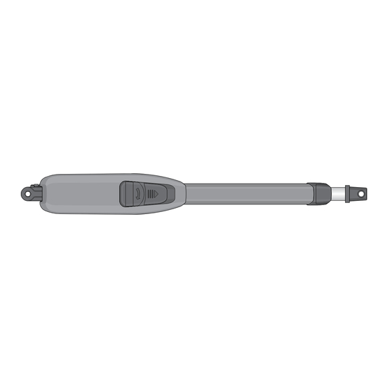
Actuator Arm and
Control Box Mounting
To wire this operator and complete the installation, refer to a specific control box "Wiring/Owner's manual".
EXTERNAL ENTRAPMENT PROTECTION MUST be
installed or the gate operator WILL NOT function.
Date Installed:
Installer/Company Name:
Phone Number:
Leave Manual with Owner
UL 325 Compliant
THIS PRODUCT IS TO BE INSTALLED AND SERVICED BY A TRAINED GATE SYSTEMS TECHNICIAN ONLY.
Visit www.dkslocator.com to find a professional installing and servicing dealer in your area.
Circuit Board
Serial Number
and Revision Letter:
Copyright 2017 DoorKing, Inc. All rights reserved.
Vehicular Swing Gate Operator
6005
6005
6005
6005-065-M-12-17
Advertisement
Table of Contents

Related Manuals for DKS 6005


Summary of Contents for DKS 6005
- Page 1 Actuator Arm and 6005 6005 6005 Control Box Mounting Vehicular Swing Gate Operator To wire this operator and complete the installation, refer to a specific control box “Wiring/Owner’s manual”. 6005-065-M-12-17 EXTERNAL ENTRAPMENT PROTECTION MUST be installed or the gate operator WILL NOT function.
-
Page 3: Specifications
6005 SPECIFICATIONS Class of Operation Model 6005 - UL 325 Class I Type of Gate Vehicular Swing Gates Only Actuator Arm Voltage 24 VDC Current 3 Amps Maximum Thrust 300 daN Max Gate Weight 500 Lbs. Max Gate Length 14 Feet Useful Rod Stroke 15.7 inches of travel... - Page 4 Mounting 6005 Mounting 115 VAC Control Box Mounting Solar Control Box Install Warning Signs In-Ground Loops Entrapment Protection Device Locations Accessory Items 6005 Primary/Secondary 4302 Circuit Board Connection Quick Guide for 6005 Limit Sensors For installers familiar with DoorKing products. 6005-065-M-12-17...
-
Page 5: Astm F2200 Standard For Gate Construction
A wireless contact sensor shall function under the intended end-use conditions. 6. One or more contact sensors shall be located at the bottom edge of a vertical barrier (arm). 6005-065-M-12-17... -
Page 6: Important Notices
Do not allow children to play in the area of the operator or to play with any gate-operating device. • To remove the gate operator from service, operate the gate to the full open position and then shut off power to the operator at the service panel. 6005-065-M-12-17... -
Page 7: Ul 325 Entrapment Protection
Type C - Inherent force limiting, inherent adjustable clutch or inherent pressure relief device. Type D - Actuating device requiring constant pressure to maintain opening or closing motion of the gate. * B1 and B2 means of entrapment protection must be MONITORED. 6005-065-M-12-17... -
Page 8: Glossary
ENTRAPMENT - The condition when an object is caught or held in a position that increases the risk of injury. 6005-065-M-12-17... -
Page 9: Swing Gate Requirements
NOT required for this area. If distance is less than 16 inches, entrapment protection in this area is required. ASTM F2200 7.1.1.2 Not Allowed Gates shall have smooth bottom edges, with vertical bottom edged protrusions not exceeding 0.50 inches. ASTM F2200 4.3 6005-065-M-12-17... -
Page 10: Swing Gate Protection
Minimizes the potential of the gate when a vehicle is exiting the striking vehicular or other traffic REQUIRED property. that loops cannot sense. Monitored for operator device helps protect against to function. entrapment when needed. 6005-065-M-12-17... -
Page 11: Installation
Placing hinges close to the corner can eliminate a potential entrapment Mounting area (See Swing Gate Requirements on page 7). Bracket Short 6005 Assembly and Manual Release Limit Cover Actuator Arm Assembly Limits Adjustment Snap ring pliers required for assembly. - Page 12 7 1/4” 1 3/4” Min Ideal 2 3/4” Do not install the 6005 in fully extended (Bottomed out) position. This will damage the arm. See page 12 to prevent this from happening. IMPORTANT: Mounting Brackets to Surfaces A + B = 14 1/2”...
-
Page 13: Operator Mounting Options
Operator Mounting Options If the mounting post dimensions or the hinge position do not allow the installation of the 6005, a recess should be created in the mounting post to maintain the desired dimensions. The recess should big enough for easy installation, and use of the 6005’s manual release. -
Page 14: Mounting 6005
Welding Brackets to Surfaces If brackets are going to be welded to the gate and/or wall, only tack weld the brackets with the 6005 attached. Protect the 6005 from welding sparks during tack welding. -
Page 15: Mounting 115 Vac Control Box
Position the desired control box on the wall, close enough to the 6005 so the primary actuator cable can be easily routed inside the box. -
Page 16: Mounting Solar Control Box
Boxes Input Power Conduit Conduit Primary 6005 Cable Sweep Elbow 3/4” conduit From Secondary 6005 if Installed (See previous page) recommended. o l e Solar Cabinet t i n Mounting Holes b i n and Conduit Holes b i n... -
Page 17: Install Warning Signs
They will reverse the cycling of the gate gate. Reverse loops work in conjunction with while a vehicle is in or near the gate’s completely opened by the time the shadow loop and both should be used. swing pathway. you drive up to it (Free exit). 6005-065-M-12-17... -
Page 18: Entrapment Protection Device Locations
REQUIRED. Potential Entrapment Area Closing Gate Potential Entrapment Area: If the CLOSING gate could cause an entrapment, then installation of a MONITORED entrapment protection device is REQUIRED. Monitored Reversing Potential Edge Entrapment Area Monitored Photo Sensor 6005-065-M-12-17... -
Page 19: Accessory Items
Accessory Items UL 325 Monitored Entrapment Protection Devices available for the model 6005 swing gate operator. Type B2 Contact Sensors (Reversing Edge) Miller Edge Sensing Edges - all models with a T2 (resistive) termination. Miller Edge Monitored Gate Link Model MGL-K20... -
Page 20: Primary/Secondary 4302 Circuit Board Connection
6005 Primary/Secondary 4302 Circuit Board Connection DoorKing 7-Wire (Terminated) Orange Wire Brown 1 Interconnection Cable (Terminated) Green Wire Blue 2 Red 3 (Terminated) Orange Wire Yellow 5 Open Beam (Terminated) Green Wire Close 1476-010 Beam Green/Yellow 7 Junction Box Secondary Connection... -
Page 21: Quick Guide For 6005 Limit Sensors
Cover Re-lock 6005 and re-install the limit cover. Cable Close Switch Adjust the secondary 6005 limit sensors if dual actuators have been installed. DIP-switch SW 1, switch 2 controls Limit Adjustments secondary 6005 opening direction. DIP-switch SW 1, switch 7 MUST be ON when using dual actuators. - Page 22 Actuator Arm and 6005 6005 6005 Control Box Mounting Vehicular Swing Gate Operator To wire this operator and complete the installation, refer to a specific control box “Wiring/Owner’s manual”. 6005-065-M-12-17 EXTERNAL ENTRAPMENT PROTECTION MUST be installed or the gate operator WILL NOT function.
Need help?
Do you have a question about the 6005 and is the answer not in the manual?
Questions and answers