Table of Contents
Advertisement
Advertisement
Table of Contents

Related Manuals for DKS 1520 Series


Summary of Contents for DKS 1520 Series
- Page 1 Owner’s Manual Series 1520 Stand Alone Proximity Card Reader and Weigand Controller DoorKing, Inc. 120 Glasgow Avenue Inglewood, California 90301 U.S.A. Phone: 310-645-0023 Fax: 310-641-1586 www.doorking.com P/N 1520-065 REV C, 5/02 Copyright 2001 DoorKing, Inc. All rights reserved.
- Page 2 Page 2...
- Page 3 Use this manual with the following models 1520-080, 1520-082, 1520-083 Stand Alone Proximity Card Reader Systems 1520-081 Stand Alone Weigand Device Controller. DoorKing, Inc. reserves the right to make changes in the products described in this manual without notice and without obligation of DoorKing, Inc. to notify any persons of any such revisions or changes.
- Page 4 Page 4...
-
Page 5: Table Of Contents
Table of Contents System Features...............................6 Important Information..............................7 Printer Information ..............................8 SECTION 1 – INSTALLATION Dimensions...............................9 1520-080 Card Reader Installation ......................10 1520-081 Weigand Controller Installation ....................11 Memory Chip Installation..........................12 Terminal Description ..........................13 Detail Wiring .............................14 SECTION 2 – PROGRAMMING Master Code .............................15 Relay Strike Time .............................15 Time and Date ............................15 Time Zones... -
Page 6: System Features
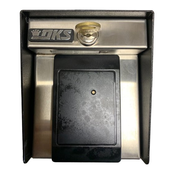
The 1520 series are offered in two different packages. The 1520-080 is a complete proximity card access system and includes a 4-5 inch read range proximity reader mounted on a lighted, stainless steel faceplate and steel enclosure. -
Page 7: Important Information
IMPORTANT INFORMATION • Prior to starting the installation, become familiar with the instructions, illustrations and wiring diagrams in this manual. • Never mount this device to a moving gate or gate panel, or next to a gate that causes vibration to the fence, such as a spring-loaded pedestrian gate. Continuous vibration from moving or slamming gates can cause damage to the unit in time. -
Page 8: Printer Information
PRINTER INFORMATION The 1520 can be connected directly to a serial printer to print transactions in real time mode as they occur, or to print the data stored in the transaction buffer when commanded. For a complete list of all printer functions, see page 20. -
Page 9: Section 1 - Installation
SECTION 1 - INSTALLATION Dimensions 5 1/4 4 3/8 3 1/4 Stand Alone Proximity Card Reader 5 1/4 4 3/4 Stand Alone Weigand Controller Page 9... -
Page 10: 1520-080 Card Reader Installation
1520-080 Card Reader Installation Do not mount the card reader to a moving gate, or immediately next to a gate panel or pedestrian gate. Continuous vibration from slamming gates and vibration can cause damage to the system over time. WARNING! If the card reader is used to activate a vehicular gate operator, it must be mounted a minimum of 10 feet away from the gate and gate operator, or in such a way that the user cannot come into contact with the gate or gate operator while using the device. -
Page 11: 1520-081 Weigand Controller Installation
1520-081 Weigand Controller Installation Open the faceplate of the controller with the keys provide so that the programming keypad is exposed. Remove four (4) 6-32 x ¼ screws from the corners of the keypad mounting plate. Save these screws as they will be used to re-install the mounting plate. Carefully remove the keypad and circuit board assembly and set it aside. -
Page 12: Memory Chip Installation
Memory Chip Installation The memory chip for this system is packaged in a separate box and must be installed prior to powering the system. Memory chips are static sensitive. Handle them with care! Never install the memory chip with power applied to the controller. Remove the keypad mounting plate from the back box by removing the small screws located in each corner. -
Page 13: Terminal Description
Terminal Description TERMINAL DESCRIPTION 16 VAC, 20 VA Input Power or 12-24 VDC. 16 VAC, 20 VA Input Power or 12-24 VDC. Earth Ground Only Relay Common – 30 Volt, 1 Amp maximum. Relay Normally Closed – 30 Volt, 1 Amp maximum. Relay Normally Open –... -
Page 14: Detail Wiring
Detail Wiring Model 1520 Card Reader / Controller Detail Wiring LOCK STRIKE/ MAG LOCK PRNTR CARD INPUT 9 10 11 12 13 14 15 16 17 18 DOORKING 1520-010 16 Volt, 20 VA UL Listed Transformer. 12-24 VDC may also be used to power the 1520. Wire size determines maximum wire run distance. -
Page 15: Section 2 - Programming
SECTION 2 - PROGRAMMING Master Code The Master Code is a four-digit number that is used to access all programming functions of the 1520 controller. The default factory master code is set to 9999. We suggest that you program a new master code once the system is installed. -
Page 16: Time Zones
Time Zones There are two types of time zones that can be used with the 1520 controller; CARD time zones and HOLD time zones. CARD time zones are applied to the individual card codes programmed into the system and HOLD time zones activate and deactivate the relay in the 1520 at predetermined times. There are six CARD time zones. -
Page 17: Card Code Programming
Card Code Programming In the following programming sequence, the term “card code” is also used to reference any 26-bit weigand device code that is being used with the 1520 controller. For example, digital entry codes or RF transmitter codes are also referred to as “card codes.” Card codes are always five-digits in length. -
Page 18: Deleting A Single Card Code
2.5.3 Deleting a Single Card Code This programming sequence deletes a single card code and takes it completely out of memory to free up space for other card codes. Card codes not programmed in the 1520 will not print or be stored in the transaction buffer. -
Page 19: Timed Anti-Pass Back
Timed Anti-Pass Back The 1520 controller has a timed anti-pass back feature that will prevent a card code from being used within a period on time from the last use of the card code. To use the anti-pass back feature, you must set the time and date (section 2.3), set the pass back time (1 to 59 minutes) and turn the anti- pass back feature ON. -
Page 20: Section 3- Print Functions
SECTION 3 – PRINT FUNCTIONS The table list the many different print functions that the 1520 controller can perform. After each function is complete, a long beep will sound. Keypad Entry Function *22 + master code Prints all card codes currently stored in the system memory. *06 + master code Prints all facility codes currently stored in the system memory. - Page 21 Page 21...
Need help?
Do you have a question about the 1520 Series and is the answer not in the manual?
Questions and answers