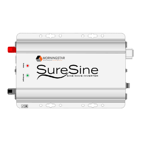
Morningstar SureSine 150W Quick Start Manual
Hide thumbs
Also See for SureSine 150W:
- Quick start manual (2 pages) ,
- Installation and operation manual (66 pages) ,
- Quick start manual (2 pages)
Table of Contents
Advertisement
Quick Links
Specifications*:
Rated Power
150 W / 300 W
Battery Voltage
12 Vdc, 24 Vdc, or 48 Vdc
120 Vac / 60 Hz, 127 Vac / 60 Hz,
AC Output Voltage (Vac) /
Frequency
or 230 Vac / 50 Hz
*Partial Specification List only. For the complete list of specifications, see the SureSine Installation and Operation's Manual.
DIP Switch Settings:
DIP 1:
OPERATIONAL
1 2 3 4 5 6 7 8
CONTROL
1 2 3 4 5 6 7 8
DIP 1 ON =
DIP 1 OFF =
Digital Control
Switch Control
DIP 2:
ALARM
1 2 3 4 5 6 7 8
1 2 3 4 5 6 7 8
SOUND
DIP 2 OFF = Alarm
DIP 2 ON = Alarm
is Disabled
is Enabled
DIP 3 & DIP 7:
NOT USED
(DEFAULT IS
1 2 3 4 5 6 7 8
1 2 3 4 5 6 7 8
OFF)
DIP 4:
LOW VOLTAGE
DISCONNECT
1 2 3 4 5 6 7 8
1 2 3 4 5 6 7 8
(LVD)
DIP 4 OFF = Custom
DIP 4 ON = Presets
LVD Default Setting (DIP Switch 4 OFF) = 11.8 V, 23.6 V, or 47.2 V
LED Indications:
STATUS LED
1
AC Output LED
Operation or State
No power or Battery
OFF
OFF
below 9.5 V
GREEN
OFF
AC Output OFF
GREEN
GREEN
AC Output ON
GREEN
GREEN (Blink)
2
AC Standby Mode
Low Voltage Disconnect
GREEN
RED (Blink)
2
(LVD) Warning
Low Voltage Disconnect
GREEN
RED
(LVD)
RED
RED (Blink)
2
Recoverable Fault
RED
RED
Critical Fault
1
The Status LED flickers ON very briefly when the LED is OFF. The Status LED flickers OFF
very briefly when the LED is GREEN or RED solid. The "heartbeat" occurs every 5 seconds.
Contact Information:
Technical Support: morningstarcorp.com/support
Phone: 1-215-321-4457
4
© 2022 Morningstar Corporation. All Rights Reserved.
Communication
Remote Switch,
Options
Bluetooth, EIA-485, MS-CAN
AC Interface
Hardwire
Options
DIP 5:
LOW VOLTAGE
DISCONNECT
1 2 3 4 5 6 7 8
(LVD) PRESETS
• For 12 Vdc Systems:
DIP 5 OFF = 10.5 V
• For 24 Vdc Systems:
DIP 5 OFF = 21.0 V
• For 48 Vdc Systems:
DIP 5 OFF = 42.0 V
DIP 6:
STANDBY
MODE
1 2 3 4 5 6 7 8
DIP 6 OFF =
AC Output
Always ON
DIP 8:
BLUETOOTH
COMMUNICA-
1 2 3 4 5 6 7 8
TIONS
DIP 8 OFF =
Bluetooth Disabled
DIP Switch 8 must be set before connecting DC power.
If changed during operation, a power cycle is required.
AC Output Mode Switch:
ON
OFF
(Front View)
(Front View)
Put the switch in
Press the |
a neutral position
I
I
O
O
(Side View)
(Side View)
3
II
II
3
0.5 Hz. Rate
2
3
See the SureSine Inverter Installation and
Operations Manual for details.
5024876
1 2 3 4 5 6 7 8
DIP 5 ON = 11.5 V
DIP 5 ON = 23.0 V
DIP 5 ON = 46.0 V
IMPORTANT:
The SureSine Inverter is designed for
1 2 3 4 5 6 7 8
converting DC power to AC power only.
DIP 6 ON =
It will not charge batteries.
AC Output
OFF < 8 W
WARNING: Hazardous Voltage
The SureSine Inverter must be installed by a
qualified technician in accordance with the
1 2 3 4 5 6 7 8
electrical regulations of the country of
installation.
DIP 8 ON =
Bluetooth Enabled
CAUTION: This guide must be used with the full product manual that includes important
information. Carefully read the SureSine Inverter product manual for all specifications,
safety, regulatory and warranty information, and for all required instructions on
installation procedures, configuration, and operation.
REMOTE
Warranty Registration:
(Front View)
In the Box:
Press the | |
I
O
(Side View)
II
Screws (x4)
Terminal Connector
MS-003768 v1
Quick Start Guide
Scan QR Code to go directly
to the SureSine Inverter
Installation Manual and
warranty information online.
https://www.morningstarcorp.com/product-registration/
Tools Required:
— #2 Philips Screwdriver
— 3/16 (5 mm) & 1/8" (3.8 mm) Flathead
Screwdriver
— Drill with a 1/8" (3.8 mm) bit
— Multimeter
— Crimping Tool
SureSine Inverter
— Wrench
4-Pin Pluggable
Terminal Resistor
SureSine Inverter Models:
150 W & 300 W Models
(Hardwired Versions ONLY)
For use with 12 Vdc, 24 Vdc,
or 48 Vdc Systems
1
Advertisement
Table of Contents

Subscribe to Our Youtube Channel
Summary of Contents for Morningstar SureSine 150W
- Page 1 LED is GREEN or RED solid. The "heartbeat" occurs every 5 seconds. See the SureSine Inverter Installation and Operations Manual for details. Contact Information: #10 Mounting 4-Pin Pluggable Terminal Resistor Technical Support: morningstarcorp.com/support Screws (x4) Terminal Connector Phone: 1-215-321-4457 5024876 © 2022 Morningstar Corporation. All Rights Reserved. MS-003768 v1...
- Page 2 SureSine Inverter Quick Start Guide Minimum Ensure circuit breakers are open, IMPORTANT: Example only. Actual wiring may vary. READ the SureSine WARNING: Risk of Fire STEP disconnect switches are open, and Installation and Operations Manual for mandatory safety requirements. All Clearance AC Output All over-current protection devices and wiring must...


Need help?
Do you have a question about the SureSine 150W and is the answer not in the manual?
Questions and answers