Sign In
Upload
Download
Table of Contents
Contents
Add to my manuals
Delete from my manuals
Share
URL of this page:
HTML Link:
Bookmark this page
Add
Manual will be automatically added to "My Manuals"
Print this page
×
Bookmark added
×
Added to my manuals
Manuals
Brands
Morningstar Manuals
Inverter
SureSine 150
Installation and operation manual
Morningstar SureSine 150 Installation And Operation Manual
Hide thumbs
Also See for SureSine 150
:
Installation and operation manual
(78 pages)
1
2
3
4
5
6
Table Of Contents
7
8
9
10
11
12
13
14
15
16
17
18
19
20
21
22
23
24
25
26
27
28
29
30
31
32
33
34
35
36
37
38
39
40
41
42
43
44
45
46
47
48
49
50
51
52
53
54
55
56
57
58
59
60
61
page
of
61
Go
/
61
Contents
Table of Contents
Bookmarks
Table of Contents
Table of Contents
Introduction
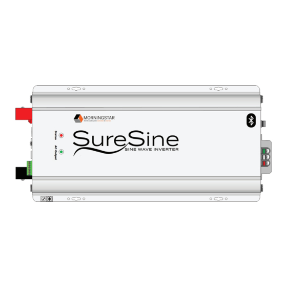
Features
Figure 1: Suresine Inverters Series
Components of the 150 W & 300 W Models
Figure 2: Suresine Inverter Features (150 W & 300 W Models)
Components of the 700 W Models
Figure 3: Suresine Inverter Features (700 W Models)
Components of the 1,000 W to 2,500 W Models
Figure 4: Suresine Inverter Features (1,000 W to 2,500 W Models)
Dimensions of the 150 W & 300 W Models
Figure 5: Dimensions - 150 W to 300 W Models
Dimensions of the 700 W to 2,500 W Models
Figure 6: Dimensions - 700 W to 2,500 W Models
Installation
Required Tools
Additional Hardware Requirements
Mounting
Figure 7: Mounting Orientation
Figure 8: Mounting Holes
Safety Considerations for Mounting
Figure 9: Minimum Clearance Requirements
Mounting Procedure
Adjusting Settings
DIP Switch Location
Figure 10: DIP Switches
DIP Switch Confi Guration Options
Figure 11: DIP Switch Confi Gurations
Remote Switch Installation (Optional)
Figure 12: Remote Switch Wiring for 150 W to 300 W Models
Figure 13: Remote Switch Wiring for 700 W to 2,500 W Models
Auxiliary Power (Optional)
Figure 14: Auxiliary Power Terminals on 700 W to 2,500 W Models
Inverter Wiring
Terminal Torque Requirements
Over-Current Protection Requirements
DC and AC Conductor Sizing Requirements
Grounding and Bonding Requirements
Figure 15: Internal Grounded Neutral Vs. External Grounded Neutral (Internal Neutral Ground Bond Removed)
Grounding Connections
DC Connections
Figure 16: DC Connections on 150 W & 300 W Models with Negative Grounding
Figure 17: DC Connections on 150 W & 300 W Models with Positive Grounding
Figure 18: DC Connections on 700 W to 2,500 W Models with Negative Grounding
Figure 19: DC Connections on 700 W to 2,500 W Models with Positive Grounding
AC Connections
Figure 20: AC Connections on 150 W, 300 W, & 700 W Models (with Factory Wiring)
AC Wiring
Check Wiring and Power up
Figure 21: AC Wiring
Operation
LED Indications
AC Output Mode Switch Operation
Figure 22: AC Output Mode Operation and Bluetooth Activation
Communication Options
Figure 23: Communication Port Locations
Bluetooth
To Connect the Suresine Using Bluetooth
Figure 24: Communication Using Bluetooth
Suresine Utility App
Figure 25: Suresine Utility App (Main Dashboard)
Ethernet (for Modbus™ TCP/IP)
To Connect to the Internet Using Modbus Protocols
Figure 26: Communication Using Ethernet
EIA-485 Device Communication
To Connect the Suresine Inverter to an EIA-485 Device
Figure 27: EIA-485/RS-232 Communications Adapter (RSC-1)
Figure 28: Connecting to an EIA-485 Device
Figure 29: Auxiliary Power Connections (700 W, 1,000 W, 1,250 W or 2,500 W Models ONLY)
USB Port
To Connect to the USB Port
Figure 30: USB Port Locations
MS-CAN (Future Feature)
To Connect the Suresine to Another Morningstar Device
Figure 31: Communication Using MS-CAN
To Connect the Suresine to a Morningstar Network
Firmware Update Procedure
Figure 32: Communication Using MS-CAN with Multiple Devices
Specifications
Conductor Sizing
A.1 Stranded Copper Wire Rated for 75°C
A.2 Solid Copper Wire Rated for 75°C
A.3 Stranded Copper Wire Rated for 90°C
A.4 Solid Copper Wire Rated for 90°C
Appendix B: Warranty
B.1 Claim Procedure
B.2 Warranty Exclusions and Limitations
Advertisement
Quick Links
Download this manual
MORNINGSTAR
World's Leading Solar
Controllers
&
Inverters
Installation and Operations Manual
150 W, 300 W, 700 W (12 V, 24 V, & 48 V) Models,
1,000 W &1,250 W, (24 V & 48 V) Models,
2,500 W (48 V Only) Models
September 2022 (Rev B08)
Table of
Contents
Previous
Page
Next
Page
1
2
3
4
5
Advertisement
Table of Contents
Need help?
Do you have a question about the SureSine 150 and is the answer not in the manual?
Ask a question
Questions and answers
Related Manuals for Morningstar SureSine 150
Inverter Morningstar SureSine 150 Installation And Operation Manual
Sine wave inverter (78 pages)
Inverter Morningstar SureSine 150 W Quick Start Manual
(2 pages)
Inverter Morningstar SureSine 150 W Installation And Operation Manual
(66 pages)
Inverter Morningstar SureSine 150W Quick Start Manual
(2 pages)
Inverter Morningstar SureSine 150W Quick Start Manual
(2 pages)
Inverter Morningstar SureSine-300 Repair Instructions
(9 pages)
Inverter Morningstar SureSine 300 Installation And Operation Manual
(61 pages)
Inverter Morningstar PS-MPPT-25 Installation, Operation And Maintenance Manual
Prostar mppt series solar charging system controller (43 pages)
Inverter Morningstar ProStar PS-15M Installation, Operation And Maintenance Manual
Solar controllers (25 pages)
Inverter Morningstar SUNSAVER MPPT SS-MPPT-15L Installation, Operation And Maintenance Manual
With trakstar mppt technology (34 pages)
Inverter Morningstar SUNSAVER SS-6-12V Installation And Operation Manual
Pv system controllers sunsaver series (24 pages)
Inverter Morningstar TriStar TS-MPPT-60M Installation And Operation Manual
Solar battery charger with trakstar maximum power point tracking technology (68 pages)
Inverter Morningstar SI-300-115V Installation And Operation Manual
Supersine-300 300 watt pure sine wave inverter (16 pages)
Inverter Morningstar TS-MPPT-60-600V-48-DB-TR Installation, Operation And Maintenance Manual
Solar charging system controller (45 pages)
Inverter Morningstar ProStar Technical Note
(7 pages)
This manual is also suitable for:
Suresine 300
Suresine 700
Suresine 1000
Suresine 1250
Suresine 2500
Table of Contents
Print
Rename the bookmark
Delete bookmark?
Delete from my manuals?
Login
Sign In
OR
Sign in with Facebook
Sign in with Google
Upload manual
Upload from disk
Upload from URL


Need help?
Do you have a question about the SureSine 150 and is the answer not in the manual?
Questions and answers