
Related Manuals for SeaLevel ULTRA COMM+2i.PCIe


Summary of Contents for SeaLevel ULTRA COMM+2i.PCIe
- Page 1 ULTRA COMM+2i.PCIe User Manual | 7203e © Sealevel Systems, Inc. 7203e Manual | SL9238 10/2022...
-
Page 2: Table Of Contents
APPENDIX D – ASYNCHRONOUS COMMUNICATIONS .................. 19 APPENDIX E – GROUND LOOP PHENOMENON ....................20 APPENDIX F – MECHANICAL DRAWING ......................21 APPENDIX G – COMPLIANCE NOTICES ......................22 WARRANTY ................................ 23 © Sealevel Systems, Inc. 7203e Manual | SL9238 10/2022... -
Page 3: Introduction
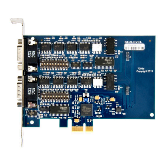
Introduction Overview The Sealevel Systems UltraCOMM+2i.PCIe is a two channel isolated PCIe Bus serial I/O adapter for the PC and compatibles. Utilizing the PLX OXPCIE952 with its industry leading16C950 based 128 byte FIFOs, it provides two field selectable RS232/422/485 serial ports supporting data rates up to 460.8K bps (RS- 422/485). -
Page 4: Before You Get Started
Before You Get Started What’s Included The UltraCOMM+2i.PCIe is shipped with the following items. If any of these items are missing or damaged, please contact Sealevel for replacement. UltraCOMM+2i.PCIe Isolated Serial Interface • Advisory Conventions Warning The highest level of importance used to stress a condition where damage could result to the product, or the user could suffer serious injury. - Page 5 EIA-232 standards. DB9 Female to DB9 Female, 72 inchLength - RS-422 207M SMPTE Cable (Item# CA190) The CA190 connects any Sealevel DB9 RS-422 device to a Sony (or compatible) 207M (SMPTE) 9 Pin connector.
- Page 6 RS-232. The TB05 includes holes for board or panel mounting. The TB05 is designed to connect directly to Sealevel DB9 serial cards or any cable with a DB9M connector. al DB9 Female to 18 Screw Terminal Block (Item# TB06) The TB05 terminal block breaks out a DB9 connector to 9 screw terminals to simplify field wiring of serial connections.
-
Page 7: Card Setup
1200 bps 3.625 2400 bps 3.625 4800 bps 1.875 9600 bps 1.875 19.2K bps 1.375 38.4K bps 1.375 57.6K bps 22.625 115.2K bps 230.4K bps 460.8K bps 2.125 921.6K bps 2.125 © Sealevel Systems, Inc. 7203e Manual | SL9238 10/2022... - Page 8 If multiple UltraCOMM+2i.PCIe adapters are configured in a RS-485 network, only the boards on each end should have jumpers T, P & P ON. Refer to the following table for each position’s operation: © Sealevel Systems, Inc. 7203e Manual | SL9238 10/2022...
- Page 9 Position 9 of SW1 and SW2 is used to control the RS-485 enable/disable functions for the receiver circuit. To select the ‘No Echo’ mode place switch position 9 to the ‘On’ position. © Sealevel Systems, Inc. 7203e Manual | SL9238 10/2022...
-
Page 10: Installation
7. The software is now installed, and you can proceed with the hardware installation. 8. Refer to the Physical Installation section to connect and install your adapter. All Sealevel Systems software drivers have been fully tested by Sealevel. Clicking ‘OK’ will not harm your system. -
Page 11: Hardware Installation
SeaCOM driver. Hardware Installation The ULTRA COMM+2I.PCIe can be installed in any of the PCI expansion slots and contains several jumper straps for each port that must be set for proper operation. -
Page 12: Technical Description
Technical Description The Sealevel Systems UltraCOMM+2i.PCIe provides a PCIE interface adapter with 2 optically isolated asynchronous serial ports which provide a versatile interface, field selectable as RS-232 for modems, printers, and plotters, as well as RS-422/485 for industrial automation and control applications. Isolation is important in installations where the equipment being connected to the PC is either far from the PC, or on a different power transformer circuit. -
Page 13: Technical Specifications
Mean Time Between Failure 800,000 hours Manufacturing All Sealevel Systems Printed Circuit boards are built to UL 94V0 rating and are 100% electrically tested. These printed circuit boards are solder mask over bare copper or solder mask over tin nickel. Power Consumption Supply line +3.3 VDC... -
Page 14: Appendix A - Troubleshooting
Appendix A – Troubleshooting Once you have confirmed that the serial adapter COM ports are listed in Device Manager, use the Sealevel WinSSD utility to verify communications. Detailed help is included in the WinSSD utility. Please set the adapters Electrical Interface for either RS-232 or RS-422. - Page 15 Change your parameters to 9600 bits per second, 8 data bits, no parity, 1 stop bit, and no flow control, as pictured below. Click ‘Apply’ and ‘OK’. In the main WinSSD window, click on the ‘BERT’ tab (Bit Error Rate test). Click on the ‘Start’ button. © Sealevel Systems, Inc. 7203e Manual | SL9238 10/2022...
- Page 16 Receive Frames will increase. The Tx and Rx Data Rates will show the calculated data rate. This verifies that the adapter is working properly. You can continue testing this port with different configurations or proceed with testing other ports, if necessary. © Sealevel Systems, Inc. 7203e Manual | SL9238 10/2022...
-
Page 17: Appendix B - Safety Instructions
6. Keep work area free of non-conductive materials such as ordinary plastic assembly aids and Styrofoam. 7. Use field service tools such as cutters, screwdrivers, and vacuum cleaners that are conductive. © Sealevel Systems, Inc. 7203e Manual | SL9238 10/2022... -
Page 18: Appendix C - Electrical Interface
(Tx+ to Rx+ and Tx- to Rx-). Four wire mode allows full duplex data transfers. RS-485 does not define a connector pin-out or a set of modem control signals. RS-485 does not define a physical connector. © Sealevel Systems, Inc. 7203e Manual | SL9238 10/2022... -
Page 19: Appendix D - Asynchronous Communications
The communication parameters are baud rate, parity, number of data bits per character, and stop bits (i.e.,9600,N,8,1). © Sealevel Systems, Inc. 7203e Manual | SL9238 10/2022... -
Page 20: Appendix E - Ground Loop Phenomenon
DC to DC converter circuit or in the opto-isolator circuit. This condition will cause data errors and possibly destruction of the receiver circuit. DATA+ DATA- Isolated Isolated Adapter Ground Adapter Isolation Barrier © Sealevel Systems, Inc. 7203e Manual | SL9238 10/2022... -
Page 21: Appendix F - Mechanical Drawing
Appendix F – Mechanical Drawing © Sealevel Systems, Inc. 7203e Manual | SL9238 10/2022... -
Page 22: Appendix G - Compliance Notices
Always use cabling provided with this product if possible. If no cable is provided or if an alternate cable is required, use high quality shielded cabling to maintain compliance with FCC/EMC directives. © Sealevel Systems, Inc. 7203e Manual | SL9238 10/2022... -
Page 23: Warranty
Sealevel's commitment to providing the best I/O solutions is reflected in the Lifetime Warranty that is standard on all Sealevel manufactured I/O products. We are able to offer this warranty due to our control of manufacturing quality and the historically high reliability of our products in the field. Sealevel products are designed and manufactured at its Liberty, South Carolina facility, allowing direct control over product development, production, burn-in and testing.
Need help?
Do you have a question about the ULTRA COMM+2i.PCIe and is the answer not in the manual?
Questions and answers