Advertisement
Quick Links
Instructions – Parts List
17:1 RATIO, WALL MOUNT
Senator Pumps
For Airless and Air–Assisted Applications
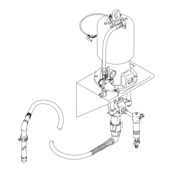
Part No. 237282, Series B
For ambient temperature spray applications.
1700 psi (117 bar, 11.7 MPa) Maximum Fluid
Working Pressure
100 psi (7 bar, 700 kPa) Maximum Air Input Pressure
Important Safety Instructions
Read all warnings and instructions in this manual.
Save these instructions.
See page 2 for Table of Contents.
GRACO INC. P.O. BOX 1441 MINNEAPOLIS, MN 55440–1441
Copyright 1988, Graco Inc. is registered to I.S. EN ISO 9001
Parts
307933M
4393B
Model 237282 Shown
Advertisement

Related Manuals for Graco 237282


Summary of Contents for Graco 237282
- Page 1 Read all warnings and instructions in this manual. Save these instructions. See page 2 for Table of Contents. 4393B Model 237282 Shown GRACO INC. P.O. BOX 1441 MINNEAPOLIS, MN 55440–1441 Copyright 1988, Graco Inc. is registered to I.S. EN ISO 9001...
- Page 2 D This equipment is for professional use only. D Read all instruction manuals, tags, and labels before operating the equipment. D Use the equipment only for its intended purpose. If you are not sure, call your Graco distributor. D Do not alter or modify this equipment.
- Page 3 Do not repair high pressure couplings; you must replace the entire hose. D Use only Graco approved hoses. Do not remove the spring guard that is used to help protect the hose from rupture caused by kinks or bends near the couplings.
- Page 4 WARNING FIRE AND EXPLOSION HAZARD Improper grounding, poor ventilation, open flames or sparks can cause a hazardous condition and result in a fire or explosion and serious injury. D Ground the equipment and the object being sprayed. Refer to Grounding on page 5. D If there is any static sparking or you feel an electric shock while using this equipment, stop spray- ing immediately.
- Page 5 NOTE: Reference numbers and letters in parentheses in the text refer to the callouts in the figures and the parts drawing. NOTE: Always use Genuine Graco Parts and Acces- sories, available from your Graco distributor. Refer to Product Data Sheet for your pump, Form No. 305790.
- Page 6 Installation Supplied Components System Accessories Refer to Fig. 2 for a typical installation of an air- assisted system. Air and Fluid Hoses Be sure all air hoses (B, K) and fluid hoses (G) are WARNING properly sized and pressure-rated for your system. Use only electrically conductive hoses.
- Page 7 Installation SUPPLIED COMPONENTS ACCESSORIES YOU MUST SUPPLY Electrically Conductive Air Hose Pump Air Line Filter Pump Air Regulator Bleed-Type Master Air Valve (for accessories) Pump Wall Bracket Air Line Drain Valve Fluid Drain Valve (required) Air Line Lubricator Fluid Filter Pump Runaway Valve 16 Suction Hose G Electrically Conductive Fluid Line...
- Page 8 Installation Model 237282 (for Ambient Temperature Spray Applications) NOTE: Refer to page 9 to convert Pump Model 237282 to a heated system. 1. Mount the pump wall bracket (3) 5 ft (1.5 m) above the floor. Be sure the wall is strong enough to...
- Page 9 Converting to a Heated System Viscon HP Heater Cord 110160 12 gauge, rated at 105_C. To convert Model 237282 to a heated circulating system, order the following parts. The heaters are WARNING available in three voltages. Specify which voltage you desire.
- Page 10 See Fig. 6. 7. Screw an elbow (24*) into the upper heater’s inlet. Attach the second heater hose (23*) to the elbow. Run this hose to the left of and behind the lower heater. Model 237282 Shown 04395B Fig. 5 10 307933...
- Page 11 Installation Installing Circulating Kit 222312 2. Screw nipple (54) and then the tee (49{) into the elbow (8) at the pump fluid inlet. Connect the adapter (14), suction hose (16), fittings (52 and 53), and tube (17) to the tee. Screw the 1 x 3/4 npt WARNING bushing (55) and then the 3/4 npt x 1/4 npt bush- ing (50{) into the branch of the tee.
- Page 12 Installation Specify desired heater voltage. See page 9. Part of heater (35). Arrow must point down. Connect to the main fluid supply line to the guns. Connect to the main fluid return line. 04398B Fig. 6 12 307933...
- Page 13 Notes 307933...
- Page 14 Pressure Relief Procedure Packing Nut/Wet-Cup Before starting, fill the packing nut (U) 1/3 full with WARNING Graco Throat Seal Liquid (TSL) or compatible solvent. See Fig. 7. SKIN INJECTION HAZARD The system pressure must be manually relieved to prevent the system from WARNING starting or spraying accidentally.
- Page 15 Operation/Maintenance Starting and Adjusting the Pump 9. Use the air regulator to control the pump speed and fluid pressure. Always use the lowest pressure 1. Be sure the air regulator and bleed-type master air necessary to achieve the desired results. Higher valve are closed.
- Page 16 Operation/Maintenance Shutdown and Care of the Pump CAUTION WARNING Never leave water or water-base fluid in the pump overnight. If you are pumping water-base fluid, flush To reduce the risk of serious injury whenever you with water first, then with a rust inhibitor such as are instructed to relieve pressure, always follow the mineral spirits.
- Page 17 Parts Model 237282, Series B Part No. Description 245166 17:1 SENATOR PUMP See manual 309340 206197 AIR REGULATOR See manual 308168 206294 BRACKET, wall, pump See the Air Regulator Detail. 210658 DRAIN VALVE; 3/8 npt(mbe) See manual 306861 Part of the wall bracket (3).
- Page 18 Included in Dual Heater Mounting Kit 222311. Required to 159801 UNION, adapter, 90_; convert Model 237282 Sprayer to a heated unit. The 3/8 npt(f) x 1/2 npsm(f) swivel heaters are not included in this kit and must be ordered 165198 NIPPLE, reducing, 3/8 npt x 1/4 npt separately, by desired voltage (see page 9).
- Page 19 Parts Dual Heater Mounting Kit, Part No. 222311 Circulating Kit, Part No. 222312 See the Check Valve Detail. Connects to the gun fluid supply line. Connects to the fluid return line. 5 (Ref) CHECK VALVE DETAIL 23* (Ref) 23* (Ref) 4397B 307933...
- Page 20 Mounting Hole Layout M8 or 5/16 in. diameter holes for heater wall brackets (or use brackets as templates to mark wall). 6 in. 12.375 in. (152 mm) (314 mm) 15 in. (381 mm) 5 in. (127 mm) 7.375 in. (187 mm) 8.5 in.
- Page 21 Pump performance data See pump manual 309340 Air consumption data See pump manual 309340 Maximum operating temperature Model 237282 (ambient temperature applications): 180_F (82_C) (heated applications): 205_F (93_C) Air inlet size 3/4 npsm(f) Fluid outlet size (at fluid filter) 3/8 npsm(f) Fluid inlet size 2 in.
- Page 22 Graco distributor to the original purchaser for use. With the exception of any special, extended, or limited warranty published by Graco, Graco will, for a period of twelve months from the date of sale, repair or replace any part of the equipment determined by Graco to be defective.
Need help?
Do you have a question about the 237282 and is the answer not in the manual?
Questions and answers