
Related Manuals for FabiaTech FX5206


Summary of Contents for FabiaTech FX5206
- Page 1 FabiaTech Corporation IPC Solution Website: http://www.fabiatech.com Email: support@fabiatech.com Small Cube System Fanless Series FX5206 User’s Manual DEC 2013 Version: 1.0 Part Number: FX5206...
- Page 2 FabiaTech shall not be reliable for technical or editorial errors or omissions, which may occur in this document. FabiaTech shall not be reliable for any indirect, special, incidental or consequential damages resulting from the furnishing, performance, or use of this document.
-
Page 3: Table Of Contents
Table of Contents FX5206 User’s Manual ......................i Chapter 1 Introducing the FX5206 System ................1 Overview..........................1 Series Comparison Table .......................2 Layout............................3 Specifications..........................4 Packing List ..........................5 Chapter 2 Hardware Installation ....................7 Before Installation ........................7 Removing Covers –Installing Hardware............8 LED Indicators & I/O Peripheral Connectors ..........11 ... - Page 4 Chapter 4 Software Installation ....................47 VGA Drivers ...........................47 WINXP Driver ......................47 Audio Driver...........................48 WIN XP Driver .....................48 LAN Driver (RTL 8111F) ......................48 WIN XP Driver .....................48 BIOS Flash Utility........................48 Watchdog Timer........................49 Watchdog Timer Setting ..................49 Setup Watchdog Timer Step - WDT0 and WDT1 ..........51 ...
-
Page 6: Chapter 1 Introducing The Fx5206 System
FabiaTech Corporation Chapter 1 Introducing the FX5206 System Overview The FX5206 is an embedded system with low-power CPU module inside. This user’s manual provides information on the physical features, installation, and BIOS setup of the FX5206. Built to unleash the total potential of the Vortex™ 86DX2 Processor, Able to support 800MGz CPU, this system supports one 10/100/1000 Base –T LAN port, PCIe Mini... -
Page 7: Series Comparison Table
FabiaTech Corporation Series Comparison Table Model FX5206 System Processor 800MHz Vortex™ 86DX2 Memory DDR2 300/333 Onboard RAM Watchdog Timer Multi I/O One RS232 Storage One CFast and SD Card USB 2.0 Port Three Audio Ear-Phone And MIC-In RJ45 LAN port... -
Page 8: Layout
FabiaTech Corporation Layout POWER LED EAR-PHONE ANTENNA ANTENNA RESET POWER SWITCH DC12~24V DC IN... -
Page 9: Specifications
FabiaTech Corporation Specifications Processor Board – Vortex™ 86DX2 Low Power 800MHz CPU with 1GB DDR2-RAM. I/O Outlets – One 10/100/1000 base-TX Ethernet LAN port with RJ45. One CRT and three USB ports (2.0) and one RS-232/422/485 serial port. Two Audio connectors for Earphone-out and Microphone-In. -
Page 10: Packing List
Verify the accessories in the package according to the packing list and see if there is anything missing or incorrect package is included. • If the cable(s) you use to install the FX5206 is not supplied from us, please make sure the specification of the cable(s) is compatible with the FX5206 system. - Page 11 FabiaTech Corporation...
-
Page 12: Chapter 2 Hardware Installation
FabiaTech Corporation Chapter 2 Hardware Installation This chapter introduces the system connectors & jumper settings, and guides you to apply them for field application. Before Installation Before installing the system, make sure to follow the descriptions below. 1. Before removing the cover, shut down the operation System and disconnect power switch off and unplug AC-to DC Adapter cable. -
Page 13: Removing Covers -Installing Hardware
On installing optional hardware, remove the covers. The following figures are to guide how to install CFast modules, SD Card, and PCIe Mini card module to the FX5206 and how to install the FX5206 fixers. (Please see the spots circled.) a. Unscrew Bottom cover and Installing CFast, SD and SIM Card The following figure guide you how to install compact flash onto the FX5206. - Page 14 FabiaTech Corporation b. Installing PCIe Mini Card Module You may extend additional PCIe mini card module and SIM card to FX5206. Connect the antenna cable from backside antenna hole to GPRS module and installing the SIM card to SIM socket. See as following figure and rear pictures.
- Page 15 FabiaTech Corporation c. Installing the universal fixers Please refer to the down side figure for installing the FX5206 with universal fixers. c1. FX5311K1 – Panel Back Mounting (VESA Mount 75*75) c2. AK1009 Din-Rail Kit M3*P0.5...
-
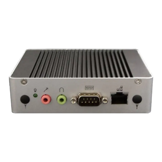
Page 16: Led Indicators & I/O Peripheral Connectors
The Power LED has two distinctive statuses: Off for inactive operation and light for activity. View from the front and back side, If you are connecting the monitor, LAN, audio, COM and USB to the FX5206. See following figure and a side pictures. POWER LED... - Page 17 FabiaTech Corporation A VGA (CRT) connector is provided for VGA signals. DB15 Signal Green Blue Hsync Vsync DDC Data DDC Clock 5 & 10 Digital Ground 6,7,8 Analog Ground Others Not Used Connecting the COM port The COM1 (DB9) is designed for multiple proposes, It’s can select RS-232/422/485 by BIOS setting.
- Page 18 FabiaTech Corporation Connecting the USB Ports The FX5206 supports a three port USB connector. Any USB device can be attached to USB ports with plug-and-play supported. USB#1~4 Signal Pin 1 USBV Pin 2 USBD- Pin 3 USBD+ (Front View) Pin 4...
-
Page 19: Connecting The Dc Power And Power Switch
DC power connector then turn on the Power Switch, when you final installed system hardware device. Power Switch: On/Off Reset Push Button The FX5206 has a push button switcher for system reset; Push and release the button will cause hardware reset of FX5206 and restart system booting. Reset Push Button: Restart... -
Page 20: Jumper Setting
FabiaTech Corporation Jumper Setting The JP1 is select RS485 terminator resistor for COM1, and J3 is used to connect an external battery. J3: external battery You can pull plug external battery to clear CMOS data. The CMOS stores information like system date, time, boot up device, password, IRQ… which are set up with the BIOS. - Page 21 FabiaTech Corporation...
-
Page 22: Chapter 3 Bios Setup
FabiaTech Corporation Chapter 3 BIOS Setup This chapter describes the BIOS setup. Overview BIOS are a program located on a Flash memory chip on a circuit board. It is used to initialize and set up the I/O peripherals and interface cards of the system, which includes time, date, hard disk drive, the ISA bus and connected devices such as the video display, diskette drive, and the keyboard. -
Page 23: Bios Functions
FabiaTech Corporation BIOS Functions On the menu, you can perform the following functions 1. Main 2. Advanced CPU Configuration IDE Configuration Remote Access Configuration USB Configuration 3. Boot Boot Settings Configuration Boot Device Priority Hard Disk Drives CD/DVD Drivers 4. Security... -
Page 24: Keyboard Convention
FabiaTech Corporation Discard Changes and Exit: Exit system setup without saving any changes. ESC key can be used for this operation. Discard Changes: Discard changes down so far any of the set questions. F7 key can be used this operation. -
Page 25: Main Setup
FabiaTech Corporation Main Setup This section describes basic system hardware configuration, system clock setup and BIOS version information. If the CPU board is already installed in a working system, you will not need to select this option anymore. System Memory... -
Page 26: Advanced Setup
FabiaTech Corporation Advanced Setup Select the Advanced tab from the setup screen to enter the Advanced BIOS Setup screen. You can select any of the items in the left frame of the screen, such as USB Configuration, to go to the sub menu for that item. You can display an Advanced BIOS Setup option by highlighting it using the <Arrow>... -
Page 27: Cpu Configuration
FabiaTech Corporation CPU Configuration You can use this screen to select options for the CPU information. Note: The CPU Configuration setup screen varies depending on the installed processor. -
Page 28: Ide Configuration
FabiaTech Corporation IDE Configuration You can use this screen to select options for the IDE Configuration Settings. Use the up and down <Arrow> keys to select an item. Use the <Plus> and <Minus> keys to change the value of the selected option. A description of the selected item appears on the right side of the screen. - Page 29 FabiaTech Corporation Hard Disk Type The BIOS supports various types for user settings, The BIOS supports <Pri Master>, <Pri Slave>, so the user can install up to two hard disks. For the master and slave jumpers, please refer to the hard disk’s installation descriptions and the hard disk jumper settings.
- Page 30 FabiaTech Corporation PCI IDE BusMaster This option is to specify that the IDE controller on the PCI local bus have bus- mastering capability. Available Options: Enabled, Disabled Default setting: Disabled OnBoard IDE Operate Mode This item specifies the Native Mode ONLY for Windows(R) XP.
-
Page 31: Remote Access Configuration
FabiaTech Corporation Remote Access Configuration This option turns on remote access support in the BIOS and is the default setting. The remote access feature requires the use of the serial port1 connector at the COM1 of system. Remote Access This field is select remote access type. - Page 32 FabiaTech Corporation Serial Port Mode This field is select Serial port1 can use any mode. Just keep in mind that the bits per second, data bits, parity, and stop bits must match terminal setting. Available Options: 115200 8,n,1/57600 8,n,1/38400,8,n,1/19200,8,n,1/9600,8,n,1 Default setting: 115200, 8, n, 1 Flow Control This field is Serial port1 can use flow control for console redirection.
-
Page 33: Usb Configuration
FabiaTech Corporation USB Configuration You can use this screen to select options for the USB Configuration. USB Host Controller Set this value to allow system to enable and disable onboard USB ports. Available Options: Disabled, and Enabled Default setting: Enabled Legacy USB Support Legacy USB Support refers to the USB mouse and USB keyboard support. - Page 34 FabiaTech Corporation USB 2.0 Controller Mode This field is configures the USB 2.0 controllers in High speed (480Mbps) or Full speed (12Mbps). Available Options: HiSpeed and FullSpeed Default setting: Hispeed BIOS ECHI Hand-Off This is a workaround for OS without ECHI Hand-Off support. The ECHI ownership change should claim by ECHI driver.
-
Page 35: Boot Setup
FabiaTech Corporation Boot Setup Select the Boot tab from the setup screen to enter the Boot BIOS Setup screen. You can select any of the items in the left frame of the screen, such as Boot Device Priority, to go to the sub menu for that item. You can display a Boot BIOS Setup option by highlighting it using the <Arrow>... -
Page 36: Boot Setting Configuration
FabiaTech Corporation Boot Setting Configuration Quick Boot This field is used to activate the quick boot function of the system. When set to Enabled, 1. BIOS will not wait for up to 40 seconds if a Ready signal is not received from the IDE drive, and will not configure its drive. - Page 37 FabiaTech Corporation Wait for ‘F1’ If Error AMIBIOS POST error messages are followed by: Press <F1> to continue If this field is set to Disabled, the AMIBIOS does not wait for you to press the <F1> key after an error message.
-
Page 38: Boot Device
FabiaTech Corporation Boot Device Use this screen to specify the order in which the system checks for the device to boot from. To access this screen, select Boot Device Priority on the Boot Setup screen and press <Enter>. First /Second Disk Boot Device Set the boot device options to determine the sequence in which the computer checks which device to boot from. -
Page 39: Usb Drives
FabiaTech Corporation USB Drives Use this screen to view the USB drives in the system. To access this screen, select USB drives on the Boot Setup screen and press <Enter>. -
Page 40: Security Setup
FabiaTech Corporation Security setup There are two security passwords: Supervisor and User. Supervisor is a privileged person that can change the User password from the BIOS. According to the default setting, both access passwords are not set up and are only valid after you set the password from the BIOS. - Page 41 FabiaTech Corporation Always: a visitor who attempts to enter BIOS or operating system will be prompted for password. Setup: a visitor who attempts to the operating system will be prompted for user password. You can enter either User password or Supervisor password.
-
Page 42: Chipset Setup
FabiaTech Corporation Chipset Setup This section describes the configuration of the board’s chipset features. • Northbridge Configuration • Southbridge Configuration... -
Page 43: Northbridge Configuration
FabiaTech Corporation Northbridge Configuration You can use this screen to select options for the North Bridge Configuration. Use the up and down <Arrow> keys to select an item. Use the <Plus> and <Minus> keys to change the value of the selected option. - Page 44 FabiaTech Corporation This field specifies the DDR Memory Timing: write Recovery Time. Available Options: 0, 1, 2, 3, 4, 5, 6, and 7 Default setting: 7 tRFC This field specifies the DDR Memory Timing: REF/ACT to REF/ACT delay. Available Options: 1 ~ 63.
- Page 45 FabiaTech Corporation VGA Configuration This field item is for VGA display. NB VGA This field specifies which VGA display will be used when the system is boot. Don’t select Disabled the NB VGA, it’s will be blinking on the VGA Display.
-
Page 46: Southbridge Configuration
FabiaTech Corporation Southbridge Configuration You can use this screen to select options for the South Bridge Configuration. South Bridge is a chipset on the motherboard that controls the basic I/O functions, LAN port, and audio function. SB HD Audio This field specifies the internal Audio Control. - Page 47 FabiaTech Corporation Serial Port Configuration This section describes the function of Serial ports settings. SB Serial Port 1 These fields select the I/O port address for Serial port. Available Options: Disabled, 3F8, 2F8, 3E8, and 2E8. Default setting: 3F8H IRQ Select This field is the Serial port 1 Interrupt.
- Page 48 FabiaTech Corporation COM1 Port Select These fields item can select RS-232, RS-422 and RS-485 of select port 1. Available Options: RS-232, RS-422 and RS485 Default setting: RS-232...
- Page 49 FabiaTech Corporation Watchdog Configuration Watchdog 0/1 Function This field specifies the Enabled or Disabled of the Watchdog Function. Available Options: Disabled and Enabled Default setting: Disabled Watchdog 0/1 Signal Select This field is the Select IRQ, NMI or Reset signal trigger of onboard watchdog.
- Page 50 FabiaTech Corporation SB PCIE_LAN Configuration OnBoard PCIE_LAN(RTL8111F) The onboard LAN corresponding PCI Express, this item allows users to enable or disable on board LAN. Available Options: Disabled, and Enabled Default setting: Enabled PXE LAN Boot ROM Controller This field specifies the PXE boot ROM of the onboard LAN chip.
- Page 51 FabiaTech Corporation...
-
Page 52: Chapter 4 Software Installation
FabiaTech Corporation Chapter 4 Software Installation The enclosed diskette includes FX5206 VGA, Audio, and LAN driver. To install and configure you FX5206 system, you need to perform the following steps. VGA Drivers WINXP Driver Step 1: To install the VGA driver, insert the CD ROM into the CD ROM device, and enter DRIVER>VGA>... -
Page 53: Audio Driver
FabiaTech Corporation Audio Driver WIN XP Driver Step 1: To install the AUDIO driver, insert the CD ROM into the CD ROM device, and enter DRIVER>AUDIO>ALC888>WIN2K&XP. Step 2: Execute SETUP.exe file. Step 3: The screen shows the SETUP type. Press any key to enter the main menu. -
Page 54: Watchdog Timer
This section describes how to use the Watchdog Timer 0 and Watchdog Timer 1, including disabled, enabled, and triggers functions. The FX5206 is equipped with a programmable time-out period watchdog timer. User can use the program to enable the watchdog timer. Once you have enabled the watchdog timer, the program should trigger it every time before it times out. - Page 55 FabiaTech Corporation Watchdog timer – WDT0 and WDT1 WDT 0 WDT 1 D7…D0 D7…D0 D7…D0 Counter [MSB …LSB] For example: WDT 0 WDT 1 30.5 μsec 61.0μsec 7.8 m sec 15.6 m sec 2 sec 4 sec 512 sec Select Watchdog Report Signal - WDT0 and WDT1...
-
Page 56: Setup Watchdog Timer Step - Wdt0 And Wdt1
FabiaTech Corporation NOTE: 1. If you program the watchdog to generate IRQ15 signal when it times out, you should initial IRQ15 interrupt vector and enable the second interrupt controller (8259 PIC) in order to enable CPU to process this interrupt. An interrupt service routine is required too. - Page 57 FabiaTech Corporation Watchdog Timer Enabled To enable the watchdog timer 0 (WDT 0), you have to output a byte of timer factor to the watchdog register whose index address is 22h and data port is 23H. The following is an Assemble program, which demonstrates how to enable the watchdog timer and set the time-out period at 4 seconds.
- Page 58 FabiaTech Corporation Watchdog Timer Trigger After you enable the watchdog timer, your program must write the same factor as enabling to the watchdog register at least once every time-out period to its previous setting. You can change the time-out period by writing another timer factor to the watchdog register at any time, and you must trigger the watchdog before the new time-out period in next trigger.
- Page 59 FabiaTech Corporation WDT1 setup Step: 1. Write time into register 6Ah-6Ch. 2. Select signal from register 69h. 3. Set register 68h bit 8 to enable WDT1. To clear the watchdog timer counter: 1. Write any value to register 67H Watchdog Timer Enabled To enable the watchdog timer 1 (WDT 1), you have to output a byte of timer factor to the watchdog ports address is 68h.
-
Page 60: Chapter 5 Technical Reference
FabiaTech Corporation Chapter 5 Technical Reference This section outlines the errors that may occur when you operate the system, and also gives you the suggestions on solving the problems. Topic include: Trouble Shooting for Post Beep & Error Messages Technical Reference Trouble Shooting for Post Beep and Error Messages The following information informs the Post Beep &... - Page 61 FabiaTech Corporation CMOS CHECKSUM ERROR This error informs that the CMOS has corrupted. When the battery runs weak, this situation might happen. Please check the battery and change a new one when necessary. DISK BOOT FAILURE When you can‘t find the boot device, insert a system disk into Drive A and press <...
- Page 62 FabiaTech Corporation MEMORY ADDRESS ERROR When the memory address indicates error, you can use this location along with the memory map for your system to find and replace the bad memory chips. MEMORY SIZE HAS CHANGED Memory has been added or removed since last boot. In EISA mode, use Configuration Utility to re-configure the memory configuration.
-
Page 63: Technical Reference
Relative humidity 5 % to 95 % non-condensing Real-Time Clock and Non-Volatile RAM The FX5206 contains a real-time clock compartment that maintains the date and time in addition to storing configuration information about the computer system. It contains 14 bytes of clock and control registers and 114 bytes of general purpose RAM. - Page 64 FabiaTech Corporation Address Description Fixed disk type byte, drive D Reserved Equipment byte Low base memory byte High base memory byte Low expansion memory byte High expansion memory byte 19-2D Reserved 2E-2F 2-byte CMOS checksum Low actual expansion memory byte...
-
Page 65: Cmos Ram Map
FabiaTech Corporation CMOS RAM Map Register Description 00h -10h Standard AT-compatible RTC and Status and Status Register data definitions 11h – 13h Varies Equipment Bits Number of Floppy Drives 1 Drive 2 Drives Bits Monitor Type Not CGA or MDA 01 40x25 CGA... -
Page 66: I/O Port Address Map
FabiaTech Corporation I/O Port Address Map Each peripheral device in the system is assigned a set of I/O port addresses, which also becomes the identity of the device. There is a total of 1K-port address space available. The following table lists the I/O port addresses used on the Industrial CPU Card. -
Page 67: Interrupt Request Lines (Irq)
FabiaTech Corporation Interrupt Request Lines (IRQ) There are a total of 15 IRQ lines available on the Industrial CPU Card. Peripheral devices use interrupt request lines to notify CPU for the service required. The following table shows the IRQ used by the devices on the Industrial CPU Card. -
Page 68: Serial Ports
FabiaTech Corporation Serial Ports The ACEs (Asynchronous Communication Elements ACE1 to ACE2) are used to convert parallel data to a serial format on the transmit side and convert serial data to parallel on the receiver side. The serial format, in order of transmission and reception, is a start bit, followed by five to eight data bits, a parity bit (if programmed) and one, one and half (five-bit format only) or two stop bits. - Page 69 FabiaTech Corporation Bit 1: Enable Transmitter Holding Empty Interrupt (ETBEI) Bit 2: Enable Receiver Line Status Interrupt (ELSI) Bit 3: Enable MODEM Status Interrupt (EDSSI) Bit 4: Must be 0 Bit 5: Must be 0 Bit 6: Must be 0...
- Page 70 FabiaTech Corporation Bit 5: Stick Parity Bit 6: Set Break Bit 7: Divisor Latch Access Bit (DLAB) MODEM Control Register (MCR) Bit 0: Data Terminal Ready (DTR) Bit 1: Request to Send (RTS) Bit 2: Out 1 (OUT 1) Bit 3: Out 2 (OUT 2)
- Page 71 FabiaTech Corporation Bit 4: Clear to Send (CTS) Bit 5: Data Set Ready (DSR) Bit 6: Ring Indicator (RI) Bit 7: Received Line Signal Detect (RSLD) Divisor Latch (LS, MS) Bit 0: Bit 0 Bit 8 Bit 1: Bit 1...
-
Page 72: Appendix
FabiaTech Corporation Appendix Dimension a. FX5206... - Page 73 FabiaTech Corporation b. FX5311K1 37.2...
- Page 74 FabiaTech Corporation c. AK1009- DIN-Rail...
Need help?
Do you have a question about the FX5206 and is the answer not in the manual?
Questions and answers